
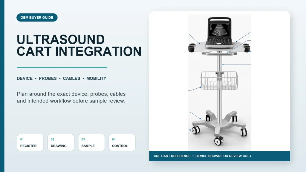
An ultrasound medical cart should be specified around the exact imaging unit, probes, cables, controls, accessories and bedside workflow—not chosen from a cart photograph alone. Before requesting a quote, provide the device footprint and mass, support points, connector locations, probe inventory, cable exits, required working height, route constraints, cleaning requirements and the parties responsible for completed-system verification.
CRF manufactures aluminum-alloy medical equipment carts for device-support projects. This guide concerns the mechanical cart and integration process; it does not establish diagnostic performance, electrical safety, clinical suitability or regulatory compliance for a completed ultrasound system.
Why “an ultrasound cart” is not a complete specification
Portable and compact ultrasound devices differ in footprint, support geometry, controls, cable exits and accessory sets. Two devices that appear similar may require different work surfaces, retainers or probe-cup positions. A suitable cart must be reviewed as part of one controlled configuration.
Common integration failures begin when a buyer confirms only the tabletop size. The equipment may physically sit on the surface while its connector is blocked, a probe cable enters a caster zone, a control cannot be reached, or an accessory collides with the column during movement.
Freeze the device and accessory register first
Create one line for every item installed, retained or carried on the cart:
- ultrasound unit and controlled model/revision;
- probes or transducers and their connectors;
- power supply, adapter or battery equipment in scope;
- printer, tablet, display or input device, if included;
- gel, wipes and consumables that require defined storage;
- probe cups, baskets, drawers, handles and cable hooks;
- buyer-supplied and supplier-supplied components; and
- items used only during transport, setup or service.
For each item, record dimensions, mass, support or mounting interface, connector side, ventilation or service zones, movement envelope and source document. Mark unavailable data as open rather than estimating it.
Review the main cart architecture decisions
| Decision area | Buyer input | Integration review |
|---|---|---|
| Work surface | Device footprint, feet, support zones and control access | Surface size, retention, edge clearance and removal path |
| Base | Intended route, bedside space and equipment arrangement | Three-, four- or five-wheel geometry, turning envelope and floor-level conflicts |
| Probe storage | Probe count, shape, cable exit and segregation needs | Cup geometry, spacing, insertion/removal path and cable protection |
| Accessory storage | Contents, access frequency and contamination controls | Basket, tray, drawer or holder position without interference |
| Height | Operator positions, device controls and viewing needs | Fixed or adjustable architecture and complete movement envelope |
| Mobility | Doorways, thresholds, lifts and room layout | Footprint, caster access, braking and maneuvering review |
| Power/cables | Exact equipment documentation and responsible electrical party | Mechanical routing, slack, retention and service disconnects |
No base or accessory arrangement is universally best. A five-caster reference does not automatically outperform a four-caster design in every room, and a three-wheel equipment cart must not be confused with a patient walker.
Match the work surface to the actual ultrasound unit
Confirm support points, not only overall dimensions
Provide a bottom view or controlled drawing showing feet, vents, service covers and protrusions. The cart surface should support the intended contact zones without blocking cooling, labels or access. Define whether the device is placed freely, retained for movement or attached through a dedicated interface.
Preserve access to controls and connectors
Map every connector and control that must remain accessible. Check the hand path as well as the static clearance. A cable can fit behind the unit yet remain difficult to disconnect without lifting the device.
Define retention without inventing compatibility
If transport retention is required, state the intended cart state and the approved attachment points. Generic straps, lips or brackets should not be assumed suitable for equipment that has not been reviewed. Retention must not press controls, cover vents or load an unapproved enclosure surface.
Plan probe and cable management together
Probe storage is an interface, not decoration. Document the probe body, insertion direction, cable exit and any separation requirement defined by the buyer or equipment documentation.
Keep cables outside mobility hazards
Route loops away from caster, brake, pinch and snag zones. Provide controlled slack for approved device motion, but avoid loose loops that can reach the floor. The cable plan should identify origin, destination, retention points, moving zones and service disconnect.
Protect connectors and service access
Do not suspend cable mass from the equipment connector. Place retainers so staff can identify and disconnect the correct cable without dismantling unrelated parts. Cable bend, separation and cleaning requirements must come from the applicable documentation rather than generic assumptions.
Review accessories as a real set
Probe cups, baskets and printers can compete for the same space. Show every selected accessory on one controlled layout. Do not combine options from different product images into an unreviewed “fully equipped” cart.
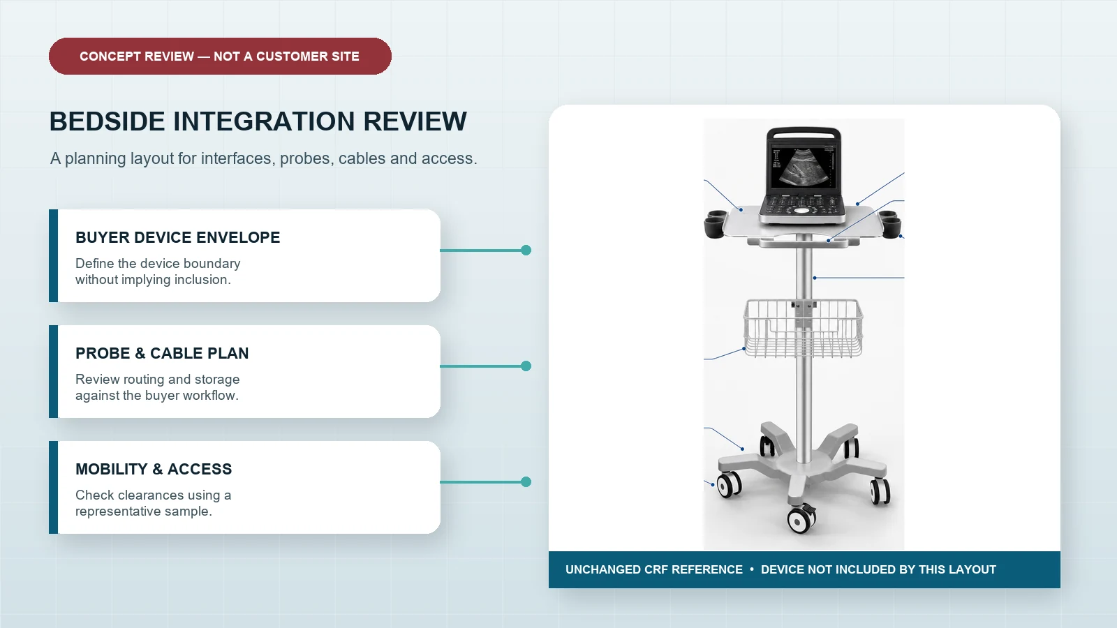
Evaluate bedside mobility and positioning
Map the route
Record doorway clearances, lift dimensions, thresholds, turns and crowded equipment zones. Compare the cart footprint and the complete loaded envelope, including handles, baskets and cable loops—not just the base.
Review the bedside working position
Define where the cart will approach, where the operator stands, where probes and controls are reached, and how nearby beds or equipment move. Check access to brakes and handles in the intended position. A compact footprint does not by itself prove workflow suitability.
Check every planned state
Review parked use, movement, height adjustment if present, accessory access, device removal, cleaning, service and packaging. A cart can be acceptable in one state and create a collision in another.
Separate mechanical integration from electrical and clinical approval
The cart supplier can review mechanical interfaces and manufacture an agreed structure. Qualified responsible parties must define any electrical architecture, powered configuration, clinical workflow, usability work, risk management, cleaning validation and destination-market obligations for the completed system.
Neat cable routing does not prove electrical compliance. A stable-looking sample does not prove a universal load or tipping margin. Diagnostic equipment shown in a scene must not be treated as included unless the quotation explicitly says so.
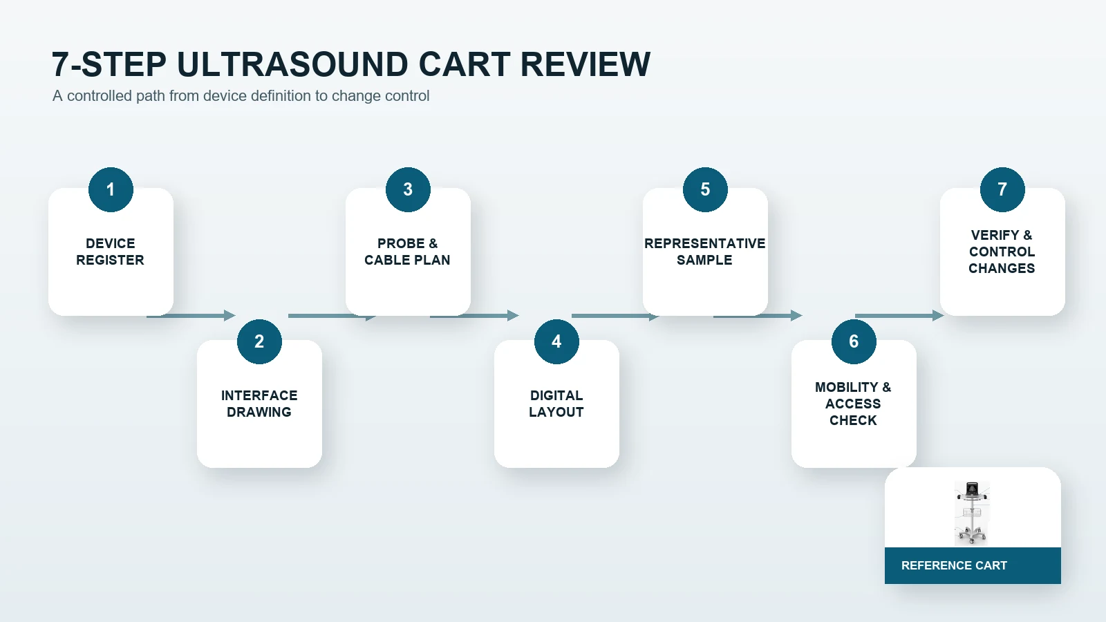
Use a controlled sample-review workflow
1. Approve the configuration register
Freeze the ultrasound unit, probes, accessories and supplier responsibilities.
2. Build an interface drawing
Show support points, retention, connectors, probe cups, storage, cable routes, movement zones and open dimensions.
3. Review the digital layout
Identify obvious collisions and access problems, while recognizing that a model does not replace physical review.
4. Assemble a representative sample
Use the intended device and accessory set, or approved representative fixtures with controlled equivalence.
5. Inspect mobility and access
Check the route, brakes, controls, probes, cables, storage, service removal and all adjustment states.
6. Verify against approved criteria
Have responsible parties define and record the applicable mechanical, electrical, usability, cleaning and other checks.
7. Release documents and control changes
Freeze drawings, BOM, assembly instructions, inspection points and open-item ownership. Reassess affected interfaces when a device or accessory changes.
Ultrasound medical cart RFQ checklist
Send prospective suppliers:
- exact ultrasound unit model and revision;
- device drawing, dimensions, mass and support-point layout;
- probe list, probe body dimensions and connector/cable information;
- required work-surface and retention approach;
- accessory, basket, drawer and printer requirements;
- cable map and service-access requirements;
- intended operator and bedside workflow;
- doorway, threshold and room constraints;
- preferred three-, four- or five-wheel architecture, if already justified;
- fixed or adjustable-height scope;
- non-powered or powered scope and responsible electrical party;
- cleaning and finish requirements defined by the buyer;
- sample and completed-system verification responsibilities;
- packaging and destination assembly scope; and
- quantity, destination market and commercial assumptions.
Ask each quote to identify included hardware, buyer-supplied equipment, engineering, tooling, sample work, packaging, verification support and exclusions separately.
A real CRF ultrasound cart reference
The CRF CA16Z130 ultrasound medical cart is a real five-caster aluminum-alloy reference. Its public product page shows a square work surface, probe cups, a wire basket, a low base and braking casters. It can start an interface discussion, but its published configuration does not prove compatibility with a buyer’s ultrasound unit or completed workflow.
Buyers can also review the CRF medical cart collection for other base and accessory architectures. Select the closest real reference, then submit controlled equipment information for review.
Limitations
This guide provides no universal load, stability margin, probe compatibility, working height, cleaning-agent compatibility, electrical rating, certification, clinical result, price, MOQ, stock or lead time. Public product information must be reconciled with the final quotation, drawing and approved sample. Responsible parties must verify the finished configuration for its intended environment and market.
FAQ
What information is needed to quote a custom ultrasound medical cart?
Provide the exact device and probe set, controlled drawings, dimensions and masses, support and retention interfaces, connectors, cable map, accessory list, workflow, route constraints, destination market and sample-review requirements.
Can the same cart support different ultrasound units?
Possibly, but each device and accessory set requires an interface and envelope review. Similar footprints do not guarantee identical feet, vents, connectors, controls, mass distribution or retention points.
Should probe holders be selected by probe count alone?
No. The probe body, cable exit, insertion/removal path, spacing and cleaning requirements also matter. Confirm the real probe set before freezing holder geometry.
Is a five-caster base always the best option?
No. Base selection depends on the complete loaded configuration, required footprint, route and verification criteria. Three-, four- and five-wheel equipment-cart architectures must be evaluated for the specific project.
Discuss an ultrasound cart configuration with CRF
Review the CA16Z130 product reference and send an RFQ through the contact page or the product page, or email info@szcrftech.com. Include the device and probe register, drawings, cable and accessory layout, route, quantity, destination and required sample-review scope. CRF can review the mechanical cart configuration and identify missing OEM inputs before quotation.