
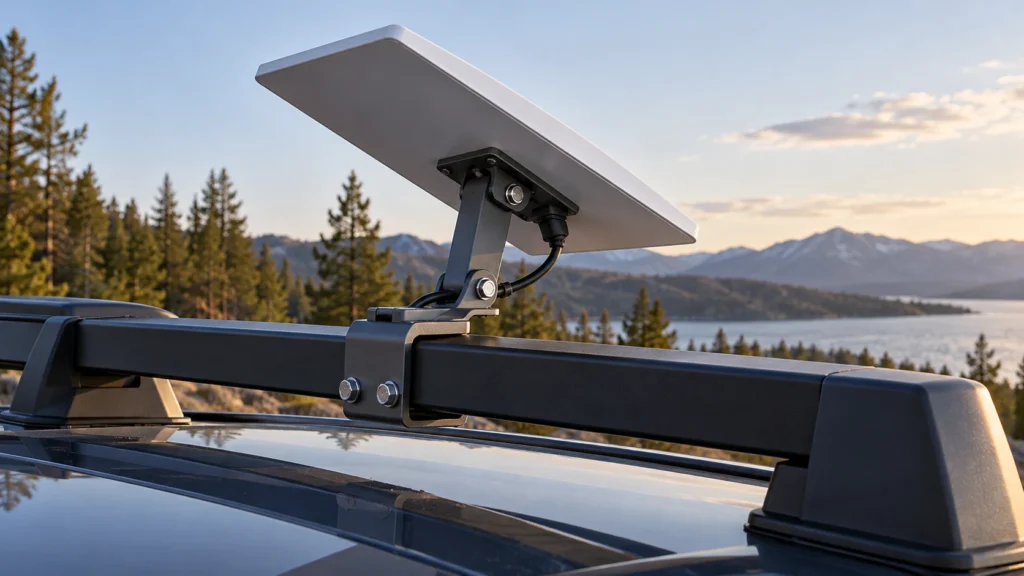
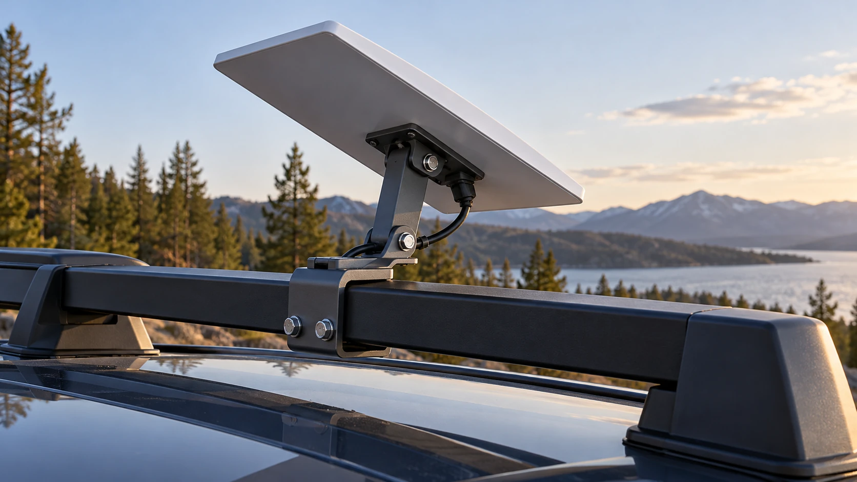
To assess a Starlink Mini roof-rack clamp, check the rack bar’s cross-section, contact faces, dimensions and surrounding clearance—not only its nominal diameter. A clamp intended for flat-faced support bars should not be treated as a round-pole adapter. Confirm the exact terminal, rack and mounting configuration before requesting a sample or approving an installation.
CRF’s adjustable aluminum vehicle pole clamp mount for Starlink Mini is the product reference for this guide. Although its title includes “pole clamp,” the detailed listing describes roof-rack support-bar installation and notes that supplier imagery excludes rounded profiles. That distinction is more useful to a buyer than the generic word “pole.”
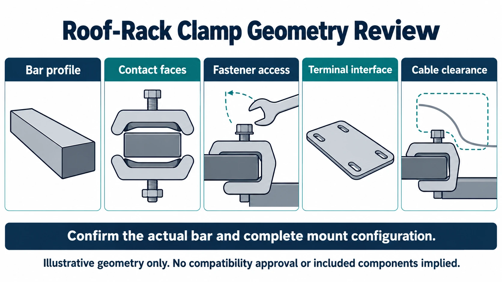
Measure the bar cross-section before choosing the clamp
A roof-rack bar may have a flat face, rounded corners, an aerofoil profile or a fully circular section. Matching one dimension does not show that the clamp can engage the intended surfaces.
Document contact faces and nearby obstructions
Provide an end-on photograph or drawing, the bar width and thickness, corner geometry and surface finish. Mark the proposed position on the rack. Include nearby rack feet, channels, accessories and vehicle bodywork that could obstruct the clamp or hand fasteners.
Do not compress a curved profile into a rectangular description just to match a catalog range. Ask CRF to review the actual geometry and identify the intended grip orientation. If the bar is rounded, treat it as outside this listing’s stated application unless a different reviewed solution is proposed.
Treat supplier dimension graphics as inputs to confirmation
The product page reports different thickness ranges for different lower-grip orientations. They are configuration-dependent listing information, not a universal fit guarantee. Request the current drawing for the selected configuration and have the supplier mark the applicable contact arrangement. Do not select an orientation by thickness alone while ignoring width, profile or surrounding clearance.
Separate rack engagement from terminal attachment
Two interfaces need independent confirmation: clamp to rack and mount to Starlink terminal. A good fit at one does not validate the other.
| Interface | Inputs to send | Confirmation to request |
|---|---|---|
| Rack to clamp | Cross-section, dimensions, finish and proposed position | Intended contact faces and grip arrangement |
| Adjustable joint | Required position and nearby obstructions | Adjustment clearance and locking procedure |
| Mount to terminal | Exact Starlink Mini hardware identification and rear photographs | Correct adapter and engagement details |
| Cable route | Actual connector and planned cable exit | Connector access and a route clear of moving joints |
The public listing contains a “For Starlink Mini 2” source reference. Do not treat ambiguous supplier generation labels as official compatibility certification. Use the actual terminal identification and interface photographs when requesting confirmation.
Review adjustment and cable clearance together
An adjustable mount needs space for both the joint and its locking hardware. Ask whether the fasteners can be accessed at the intended position without interference from the rack or vehicle. Review the complete installation envelope rather than a detached mount photograph.
Check cable access with the actual intended connector. Define support for the cable without pulling on the terminal connection or pinching it at an articulated joint. Refer to the terminal manufacturer’s current instructions for cable connection and installation requirements; an accessory description does not replace them.
The official Starlink Mini setup guide illustrates installation of Starlink’s own accessories. Its hardware arrangements and procedures should not be copied onto a third-party clamp without confirming applicability. Official accessory dimensions also do not establish the dimensions of the CRF reference product.
Parked fit review is not moving-vehicle approval
A static sample can help identify dimensional interference. It cannot by itself establish road-use suitability, wind resistance, vibration performance, rack capacity or terminal service eligibility during motion.
The CRF reference page does not provide validated speed, wind-load or vibration ratings. Do not infer those ratings from vehicle imagery, material description or hand-tightened fasteners. A qualified installer and the relevant equipment and rack suppliers should assess the complete installation and applicable requirements. Ask whether secondary retention is required and how it must be attached; do not improvise it from unverified product images.
Create a purchasing checklist with explicit exclusions
Before sample approval, record:
- Rack make, model, cross-section and measured installation position.
- Exact terminal identification and the proposed terminal adapter.
- Clamp drawing revision and intended grip orientation.
- Supplied hardware, installation instructions and adjustment procedure.
- Cable exit, connector access and surrounding clearance observations.
- Intended use, including whether the vehicle will be stationary during use.
- Evidence required for the proposed environment and any transport conditions.
- Components excluded from supply, including terminal, rack and vehicle.
Keep unresolved items visible in the RFQ. Do not replace unknown ratings with marketing adjectives such as “heavy-duty” or “all-weather.”
FAQ
Will this roof-rack clamp fit a round pole?
The CRF reference listing notes that rounded profiles are not intended. Review a separate, suitable adapter rather than assuming the title guarantees round-pole fit.
Is thickness the only measurement needed?
No. Bar width, cross-section, contact geometry, coating and fastener clearance can all affect the proposed arrangement.
Does an aluminum body establish weather or vibration performance?
No. Material identity does not establish a finished assembly’s environmental or dynamic rating. Request applicable evidence for the selected configuration.
Does a vehicle installation photograph authorize highway use?
No. A photograph is not road-use approval, a speed rating or confirmation of Starlink service eligibility during motion.
Request a geometry-based B2B quotation
Send CRF the rack cross-section, measured dimensions, installation photographs, exact Mini terminal identification and intended operating conditions. Reference the adjustable vehicle clamp product and ask for configuration-specific fit confirmation, included hardware and outstanding evidence. Contact CRF for an RFQ. Final compatibility and commercial terms require written confirmation; Starlink is a third-party brand, and compatibility language does not imply endorsement.
Request a B2B RFQ for the exact configuration and documentation scope. Images are AI-generated generic concepts, not exact CRF models, customer installations, approved procedures or performance evidence.