
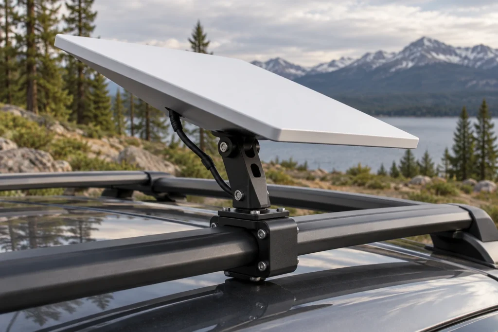
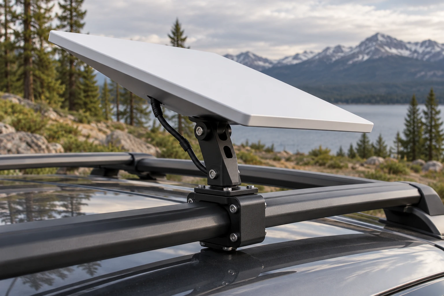
A Starlink Mini car mount should be selected by terminal version, roof-rack geometry, clamp range, interface, adjustment, cable route, hardware, installation environment and acceptance checks—not by a broad “fits vehicles” claim. For a B2B inquiry, provide the exact terminal, pole or rail dimensions, available clearances, desired orientation, exposure conditions, quantity and required evidence.
CRF has a verified adjustable aluminum-alloy clamp mount for a compatible Starlink Mini terminal on suitable vehicle roof-rack bars. That product is a real sourcing reference, not proof that it fits every vehicle, RV, ladder, rail or operating condition. Fit, installation method and permitted use must be confirmed for the project.

Define the Mounting System Before Requesting a Quote
A useful fitment brief treats the terminal, adapter, clamp, support bar, fasteners and cable route as one installation system.
Identify the exact terminal
Record the Starlink hardware name and version shown in the buyer’s documentation. Provide photographs and dimensions of the terminal interface or approved adapter. “Starlink Mini compatible” should not be assumed across unrelated terminals or third-party interfaces.
Official Starlink documentation lists distinct Mini accessories for different installation types. Use the instructions for the selected accessory or approved project mount; do not combine dimensions or installation steps from another mount type.
Describe the host structure
State whether the clamp will attach to a round tube, square bar, rectangular roof-rack crossbar, ladder rail or another defined structure. Measure:
- outside diameter for a round pole;
- width, height and corner radius for a rectangular bar;
- coating, sleeve or trim thickness;
- available straight clamping length;
- clearance around joints, brackets and nearby hardware; and
- access for tools and fastener tightening.
Do not infer fit from a vehicle model name alone. Roof racks and ladders can vary by trim, supplier and aftermarket configuration.
Compare Clamp Geometry and Contact Surfaces
Confirm the adjustment range
Ask the supplier for the supported clamp range and the exact measurement convention. Compare it with the finished support bar, including coatings or sleeves. A nominal bar size may not equal the measured outside size.
CRF’s listed clamp is not intended for rounded profiles. Confirm the permitted profile, final dimensions and included hardware in the quotation; do not apply another mount’s fit range to this configuration.
Review contact and anti-slip details
Identify where the clamp contacts the host structure. Ask whether liners, pads, sleeves or profile-specific inserts are required and whether they are included. The buyer should review whether contact pressure or movement could affect the host finish or structure.
Check fastener access
Show the available tool path around each bolt or hand-tightened fastener. Verify that a door, hatch, awning, roof box, rack joint or adjacent accessory does not block installation or inspection.
Define Orientation and Articulation
An adjustable joint can help position a terminal, but the permitted range and locking method must be documented. Provide the desired installed orientation, adjustment range, transport state and any keep-out zones.
Review:
- interface alignment with the terminal or adapter;
- joint rotation and interference through the intended range;
- fastener engagement and locking method;
- clearance between the terminal, roof and nearby accessories;
- the location of the cable connector; and
- whether the installation is fixed, removed for transport or changed between states.
Do not claim a specific angle, wind rating or in-motion suitability unless the exact configuration has supporting documentation and the intended use is permitted.
Plan the Cable Route
Cable planning belongs in the initial fitment review. Record connector dimensions, bend space and the route from the terminal to the vehicle or equipment entry point. Avoid pinch points, sharp edges, moving joints, hot surfaces and unsupported spans.
If the route enters a vehicle or enclosure, the responsible installer must select and verify the entry method, sealing components, strain relief and protection appropriate to the application. A clamp mount does not automatically make the complete cable entry waterproof.
Compare Installation Contexts
| Installation context | Fitment inputs | Questions to resolve |
|---|---|---|
| Roof-rack crossbar | Bar profile, dimensions, coating, spacing and clearances | Does the clamp match the real bar and allow tool access? |
| RV ladder or rail | Tube dimensions, material, joint locations and access | Is the selected rail an approved mounting location? |
| Utility rack | Member profile, nearby load and route | Will the mount conflict with cargo or rack joints? |
| Temporary project setup | Setup frequency, handling and inspection plan | How will fit and fastener condition be checked each time? |
| Fixed outdoor support | Substrate, exposure, access and cable entry | Are hardware, finish and installation instructions appropriate? |
These are review categories, not blanket installation approvals. Vehicle, rack and terminal instructions take priority, and a qualified installer should assess the host structure.
Ask for a Complete B2B Specification Package
A supplier response should distinguish verified facts from options. Request:
- exact product and revision identifier;
- terminal or adapter compatibility statement;
- clamp range and measurement method;
- supported bar profiles;
- overall dimensions and adjustment range;
- listed material and finish;
- fastener and included-hardware list;
- assembly and installation instructions;
- cable-clearance information;
- inspection and maintenance guidance;
- packaging contents and replacement parts; and
- available test or compliance documents relevant to the quoted configuration.
Do not convert a generic supplier statement into a tested performance claim. If weather, vibration, corrosion or dynamic use matters, define the evidence and acceptance method before ordering.
Prototype and Sample Acceptance Checklist
Identity and contents
- Product and revision match the approved quotation.
- All brackets, clamps, fasteners, pads and tools on the packing list are present.
- Materials and finish match the approved specification.
- Labels and instructions match the delivered configuration.
Fit and assembly
- The clamp fits the measured host profile without improvised parts.
- Fasteners engage correctly and remain accessible.
- The terminal or approved adapter seats as intended.
- The adjustment mechanism moves and locks through the agreed range.
- Nearby vehicle or rack features remain clear.
Cable and handling
- The connector can be inserted and removed.
- The route avoids visible pinch, abrasion and moving-joint conflicts.
- The agreed strain-relief and protection parts are present.
- Removal or transport steps match the approved procedure.
Project-specific verification
The buyer should define methods and acceptance thresholds for the actual installation, including any static, vibration, environmental or route-related checks required by responsible parties. Request documented results for the exact supplied system rather than assuming the mount has passed these checks.
Starlink Mini Car Mount RFQ Checklist
Include these inputs:
- Exact Starlink terminal and hardware version.
- Photographs and dimensions of the terminal interface or adapter.
- Vehicle, RV, rack or host-structure description.
- Pole or bar profile, outside dimensions and coating thickness.
- Available straight clamping length and tool access.
- Desired terminal orientation and adjustment range.
- Installed, parked and transport states.
- Nearby joints, cargo, hatches and keep-out zones.
- Cable connector, route, bend space and entry method.
- Outdoor exposure and cleaning conditions.
- Required material, finish and hardware documentation.
- Prototype, pilot and forecast quantities.
- Branding, packaging and spare-part requirements.
- Required test evidence and sample acceptance criteria.
- Destination market and responsible installer requirements.
Common Sourcing Mistakes
Ordering by vehicle name only
The same vehicle may use different racks or ladder systems. Measure the actual host member.
Confusing mount types
A pole clamp, roof-rack mount, magnetic base, wall mount and pivot mount use different interfaces and installation assumptions. Do not borrow specifications from another type.
Ignoring the cable until installation
Connector clearance and cable routing can change position and bracket orientation. Review them before the mount is approved.
Treating adjustability as verified retention
An articulated joint still needs a documented locking method and project acceptance checks. Adjustment range alone is not a performance result.
Assuming all outdoor uses are equivalent
Exposure, vehicle movement, rack construction and inspection access differ. Define the use case and evidence rather than relying on “weatherproof” or “heavy duty” language.
FAQ
What measurements are needed for a Starlink Mini pole mount?
Provide the host bar profile, outside dimensions, corner radius if rectangular, coating thickness, straight clamping length, nearby obstructions and tool-access space. Also identify the terminal and adapter interface.
Can a pole clamp fit both round and rectangular roof-rack bars?
Only if the quoted clamp geometry and supported profiles explicitly cover both. Confirm the real bar dimensions and required inserts or pads; do not assume interchangeability.
Is a Starlink Mini pole mount suitable for use while driving?
That cannot be inferred from the product type. Confirm the intended use, terminal and vehicle instructions, mount documentation, installation requirements and project-specific evidence. Do not use a stationary-installation assumption as an in-motion approval.
Does the mount include the Starlink Mini terminal?
Normally the terminal should be treated as separate unless the quotation explicitly lists it. Confirm every included item in writing.
Can CRF customize the clamp or interface?
CRF accepts OEM/ODM inquiries. Feasibility depends on the terminal interface, host geometry, quantity, intended environment, documentation and verification requirements.
Request a Fitment Review
Send CRF the terminal version, interface details, measured bar profile, installed and transport positions, cable route, exposure conditions, quantity and required evidence. CRF can review the inputs and discuss configuration questions before quotation.
Review the CRF adjustable vehicle clamp mount for Starlink Mini and CRF Starlink mounts as catalogue references.
This is procurement and fitment education, not installation or safety advice. Starlink is a third-party trademark; no affiliation, universal compatibility, weather rating or driving approval is claimed.
Request a B2B RFQ — share your configuration, quantity, destination market and documentation requirements.