
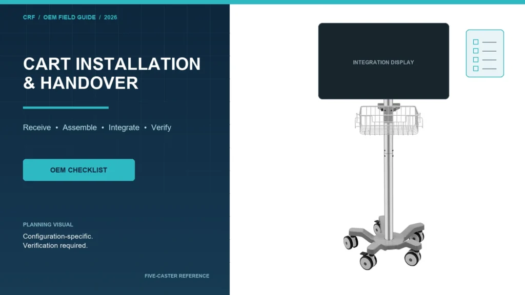
Medical equipment cart installation is the controlled conversion of delivered parts into the approved finished configuration. Handover should occur only after the exact cart, equipment, mounts, accessories, cables and documents have been checked against the project baseline and open issues have owners. The installer should not resolve missing design inputs by improvising at the destination.
CRF’s core business is custom aluminum alloy medical equipment carts with three-, four- and five-caster bases. This article covers equipment-support carts, not patient walkers. It is B2B procurement education rather than installation, electrical, clinical, safety or regulatory instruction. Installation and verification must follow approved product documentation and be performed by qualified responsible parties.
Separate delivery, assembly, integration and acceptance
These stages are related but not interchangeable:
| Stage | Core question | Typical controlled evidence |
|---|---|---|
| Delivery inspection | Did the correct package arrive without visible shortage or damage? | Packing-list reconciliation, package condition and issue record |
| Mechanical assembly | Was the cart assembled to the approved configuration? | Drawing revision, parts, fasteners, sequence and assembly record |
| Equipment integration | Were the approved device, mounts, accessories and cables installed correctly? | Device identity, interface drawing, installed configuration and responsible-party record |
| Verification and handover | Does the delivered configuration meet the project’s acceptance plan, and are open items controlled? | Checklist, results, deviations, documents, training/service handoff and sign-off |
A signed delivery note proves receipt; it does not by itself prove correct assembly, device integration or suitability for use.
Build the installation baseline before shipment
The installation team should receive a controlled package that identifies:
- cart model, serial or project identifier where applicable;
- approved cart drawing and revision;
- equipment manufacturer, model and revision;
- mounting-interface drawing and device instructions;
- included and buyer-supplied components;
- accessory and cable schedule;
- approved fasteners and source of tightening requirements;
- cart operating and transport configurations;
- assembly, inspection and maintenance documents;
- applicable acceptance procedures and responsible owners; and
- a deviation process for missing, damaged or nonconforming items.
If the device, monitor arm, tray, accessory, caster, cable or base differs from the baseline, stop the affected installation decision and route the change through qualified review. Visual similarity is not configuration approval.
Conduct a controlled receiving inspection
Check package identity and condition
Match package labels and packing lists to the order before discarding packaging. Record visible impact, moisture, opening, tilt or handling evidence when relevant to the project. Photograph authorized evidence without exposing patient, staff or confidential facility information.
Reconcile parts and documents
Confirm the cart, removed components, hardware kits, cables, accessories, manuals and records. Keep similar fasteners separated and identified. Missing parts should produce an open issue, not a local substitute selected without approval.
Preserve evidence for claims and investigation
When damage or shortage is found, retain relevant labels, packaging and photographs according to the agreed process. Identify whether the item is quarantined, conditionally accepted or released by an authorized party.
Assemble only from approved information
Establish a suitable work area
Follow the approved instructions for floor condition, workspace, lifting, handling, isolation and tools. This guide supplies no generic lifting or electrical procedure. The project owner must define who is qualified to perform each task.
Verify base, column and upper assembly
Confirm that the delivered base and caster configuration matches the drawing. Three-, four- and five-caster architectures have different geometry; do not infer the correct base from a family photograph. Check column orientation, tray or mount position, handle direction and accessory locations against the controlled views.
Control fasteners and retention
Use only the approved fastener specification and installation requirement from the responsible design documentation. Record any locking, anti-rotation or secondary-retention feature required by the project. Do not publish or apply a generic torque value across different interfaces.
Protect finish and access
Remove transport protection in the defined sequence. Check whether protective films, blocks or temporary restraints are intended to remain until later integration. Confirm that assembly does not trap packaging material, block service access or damage the aluminum finish.
Integrate equipment and cables as a complete system
Confirm device identity and mounting interface
Match the actual device to the approved interface documentation. Verify attachment location, orientation, fastener engagement, connector clearance and permitted adjustment before release. A matching hole pattern alone does not establish compatibility.
Review the loaded configuration
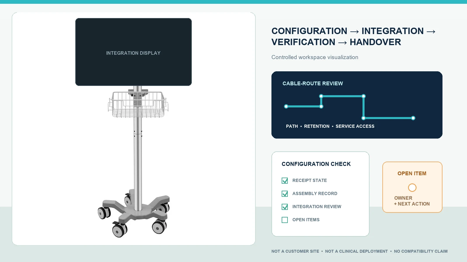
The complete installed cart—not an empty frame—should be reviewed at relevant transport, parked, operating and service states. Equipment mass, center of gravity, base dimensions, caster layout, brakes, articulated mounts and accessories all affect behavior. Do not assume a five-caster cart is inherently more stable than a three- or four-caster cart.
Route cables through every approved state
Check actual approved power and data cables for reach, retention, connector strain, bend, snag exposure and service access. Move adjustable or articulated components through their allowed positions under the project procedure. Keep excess slack away from caster, brake, pedal and handle areas.
Assign electrical and system responsibilities
A mechanical cart supplier’s scope may not include electrical integration, medical electrical system assessment, network setup or device performance verification. Identify the qualified organization responsible for each activity. Powered cart components, batteries, isolation devices or multi-socket assemblies require configuration-specific documentation and review; they must not be inferred from a non-powered cart reference.
Verify mobility, parking and workflow
The acceptance plan should define observable checks for the finished configuration. Depending on project scope, review may cover:
- start, straight travel, turns and stopping on approved routes;
- caster swivel and specified brake operation;
- handle position and user access;
- doorway, corridor, elevator and storage envelope;
- parked access to equipment controls and connectors;
- drawer, basket, arm or tray movement;
- cable behavior during movement and parking;
- transition between transport and operating states;
- cleaning and inspection access; and
- service access without uncontrolled device movement.
Use representative equipment and accessories accepted by the project team. Define route, conditions and pass/fail criteria before evaluation. A brief demonstration does not establish a universal maneuverability, stability or safety claim.
Create a handover package
Configuration record
Record the installed cart, device, mounts, accessories, cables and relevant revisions. Include approved photographs or diagrams where useful. State exclusions and buyer-supplied components.
Inspection and acceptance record
List each check, procedure reference, observed result, responsible person and date. Separate passed items, failed items, not-applicable items and checks not performed. Never convert an unchecked item into an assumed pass.
Open-item register
Each deviation needs a description, owner, containment or use restriction when applicable, due date and closure evidence. Verbal promises should not replace an issue record.
Operating, cleaning and service documents
Transfer the approved instructions applicable to the exact configuration. Identify inspection points, replacement parts, service contacts and escalation route. Do not merge generic supplier marketing into controlled instructions.
Training and responsibility handoff
If the project requires training, define audience, scope, trainer, materials and record. Training does not compensate for an unresolved design or failed acceptance item.
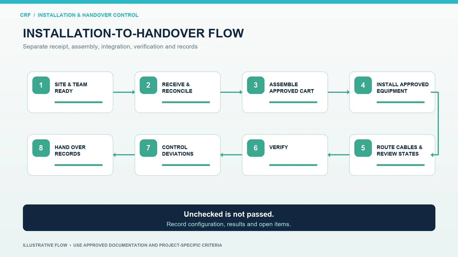
A practical installation-to-handover sequence
1. Confirm site and team readiness
Verify receiving space, intended routes, work area, approved utilities where applicable, responsible personnel and required documents before scheduling installation.
2. Inspect delivery and reconcile scope
Check package condition, configuration identity, components, tools or kits, documents and visible damage. Open issues before assembly hides the evidence.
3. Assemble the cart
Follow the approved sequence and drawing. Record the base, casters, column, tray, mount, handle, accessories, fasteners and deviations.
4. Install the approved equipment
Use the device instructions and controlled interface. Confirm orientation, retention, connector access and the loaded configuration.
5. Route cables and review all states
Check transport, parked operation, adjustment and service states for reach, retention, strain, interference and access.
6. Perform project-defined verification
Qualified parties complete the mechanical, electrical, functional, route, cleaning, regulatory or other checks assigned to them. Record results against predefined criteria.
7. Close or control deviations
Resolve failures or formally restrict release according to the project process. Do not sign a generic acceptance statement while critical scope remains undefined.
8. Transfer the handover package
Provide configuration, inspection, open-item, instruction, service and training records to the responsible owner and retain them under the agreed document-control process.
Installation RFQ and project checklist
Provide the cart manufacturer with:
- cart and equipment identifiers and revisions;
- approved device mounting and installation documents;
- complete included/excluded scope;
- base and caster configuration;
- accessory, handle, drawer, basket and cable schedule;
- assembly location and responsible installer;
- shipping state and removed-part list;
- required tools, fixtures and controlled fastener information;
- transport, operating and service configurations;
- destination route and workspace constraints;
- electrical/system integration owner, if applicable;
- project-specific inspection and acceptance plan;
- required records, language and document format;
- training, service and spare-part expectations; and
- deviation, approval and change-control workflow.
Ask each supplier to state what arrives assembled, what requires destination work and what evidence accompanies the shipment.
CRF references for installation planning
The CRF 4-Wheel Universal Ultrasound/ECG Medical Cart is a four-caster aluminum equipment-support reference. Its public page explains that the specific device dimensions, mounting interface, equipment weight, cable routing and operating environment must be reviewed and that diagnostic equipment is not included unless expressly confirmed in the quotation.
The CRF Five-Wheel Medical Monitor Cart is a separate five-caster reference. Neither page proves compatibility with an unspecified monitor, installation method, electrical system or clinical workflow. Browse the CRF medical cart collection and use the closest structure only as a starting point for a controlled OEM/ODM discussion.
Limits of this guide
This article states no fastener torque, load capacity, stability result, brake performance, route clearance, electrical result, cleaning compatibility, installation time, certification, regulatory status, medical outcome, price, stock or delivery date. It does not authorize installation of any device or powered system. Requirements, qualifications and verification depend on the actual configuration, instructions, environment and destination market.
FAQ
Who should install equipment on a medical cart?
The project should name qualified responsible parties using the device, cart and interface documentation. Responsibilities may be divided among the cart manufacturer, device OEM, authorized integrator, biomedical team or another approved organization.
Is a matching VESA pattern enough to approve a monitor installation?
No. Hole-pattern alignment does not by itself confirm fastener engagement, mount capacity, connector clearance, device orientation or suitability of the loaded cart. Use the actual device and mount documentation.
Must the loaded cart be reviewed after assembly?
The relevant project acceptance plan should address the finished configuration because equipment, accessories, cables and mounting positions can change the cart’s behavior and access. The responsible team decides the applicable checks and criteria.
What should block handover?
The project’s release procedure should define blocking issues. Common controls include unresolved identity or configuration mismatches, missing retention, visible damage, failed required checks, missing critical documentation or deviations without an authorized disposition.
Send CRF your integration and handover requirements
Explore CRF’s aluminum medical equipment carts and submit an RFQ through the contact page or a relevant product page, or email info@szcrftech.com. Include the device drawing, mounting documentation, base preference, accessory and cable schedule, shipping state, installer responsibilities and acceptance plan. CRF can review the mechanical cart scope and identify open inputs before a configuration-specific drawing, sample and handover package are agreed.