
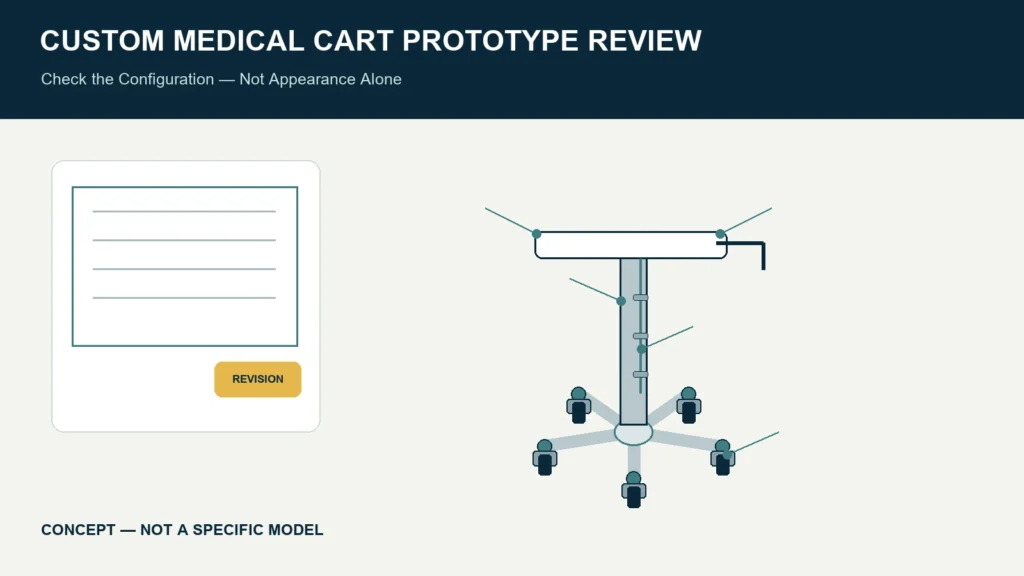
A custom medical cart prototype should be reviewed against a controlled drawing, bill of materials, approved equipment configuration and written acceptance plan—not against appearance alone. For an aluminum medical equipment cart, the prototype review should cover device fit, structure, tray and column interfaces, cable routing, three-/four-/five-caster base behavior, braking, access, finish, assembly, packaging inputs and unresolved verification responsibilities.
This guide is for OEM and procurement planning. It does not certify a prototype, prescribe a test standard or replace qualified engineering, quality, regulatory or clinical review. CRF’s main cart direction is aluminum alloy medical equipment platforms; stainless steel is only a secondary material consideration when a project specifically requires it.
Define what the prototype is meant to prove
“Prototype” can describe very different builds. Before review, label the sample’s purpose and maturity. It may be intended to confirm:
- overall envelope and equipment fit;
- mounting and accessory positions;
- user access and workflow;
- structural concept;
- manufacturing method and assembly sequence;
- cosmetic finish and branding; or
- a production-intent configuration.
Do not expect an early concept sample to prove production repeatability, and do not accept a production-intent sample while key parts are still represented by placeholders. Create a list of excluded or simulated items so no reviewer mistakes them for approved components.
Freeze the review baseline
Every observation needs a reference. The review package should identify:
- cart drawing number and revision;
- device manufacturer, model and revision;
- mounting-interface drawing;
- approved accessories and their positions;
- equipment mass and load-position inputs from responsible sources;
- base and caster configuration;
- cable and power-component schedule, where applicable;
- finish and color references;
- labeling and branding artwork revisions; and
- the prototype’s deviations from production intent.
Photographs are useful evidence, but they are not the configuration definition. A change to a bracket, caster, tray or accessory should be recorded against the controlled baseline.
Review device integration first
Mounting and retention
Confirm that the installed device matches the approved identity and orientation. Compare hole geometry, fasteners, engagement, retention and access to the responsible device documentation. A familiar plate pattern is not evidence of universal compatibility.
Check whether the device can be installed and removed using the intended service procedure without damaging finishes or dismantling unrelated components. Record prohibited contact zones and ventilation or connector clearances.
Tray and column interfaces
Inspect how the tray, bracket and column connect. Verify the location and range of any adjustment, then compare the assembled position with the drawing. Look for interference that only appears when the device, handle, accessories and cables are present together.
A dimension that passes on an unassembled part may still fail at system level. Review the complete cart in transport, operating and service configurations.
Cable management and accessories
Check every required cable and accessory, not a representative bundle. Review connector access, bend and service space, retention points, movement allowance, cleaning access and authorized disconnection steps. Do not infer electrical safety from neat routing; the responsible finished-system team must define and verify applicable electrical requirements.
Review the loaded base without ranking wheel counts
A three-, four- or five-caster base must be reviewed as part of the actual assembly. Five casters do not automatically make a cart more stable than three or four, and a lower wheel count does not automatically mean better maneuverability.
Document:
- base dimensions and caster contact layout;
- equipment and accessory positions;
- intended brake arrangement and access;
- transport and operating configurations;
- representative floors, turns and transitions; and
- any configuration that shifts the center of gravity.
The responsible engineering team should establish applicable stability, movement, brake and structural verification methods and acceptance criteria. A supplier catalog rating, component label or informal push around a workshop cannot prove finished-system acceptance.
Inspect manufacturing and assembly details
A prototype review should make the future build more repeatable. Inspect:
| Area | Review question | Record |
|---|---|---|
| Part identity | Does each reviewed part match the drawing/BOM revision? | Part and revision list |
| Fit and alignment | Do interfaces assemble without forced alignment or undocumented rework? | Gaps, interference and disposition |
| Fasteners | Are type, source, access and installation responsibility defined? | Controlled fastening record |
| Finish | Is the specified finish present on the intended surfaces without unacceptable damage? | Approved sample/finish reference |
| Labels | Are content, location and orientation controlled? | Artwork and placement revision |
| Service access | Can authorized parts be reached as intended? | Procedure and required tools |
| Assembly sequence | Is the sequence documented and repeatable? | Work-instruction actions |
Do not invent a generic torque or cosmetic tolerance during the review. Use approved specifications from the responsible design owner. Mark missing criteria as open rather than silently accepting them.
Include users, cleaning and maintenance
The FDA’s human-factors information emphasizes intended users, use environments and all user-interface points, including components that users position or manipulate and maintenance activities. For a cart prototype, involve the groups who will move, operate, clean, install and service the system where relevant to the finished product.
Observe whether users can:
- grasp the intended handle without cable or accessory obstruction;
- see the travel path and relevant controls;
- reach approved controls and connectors;
- operate the specified brakes;
- access surfaces according to the intended cleaning instructions; and
- perform authorized service tasks without improvised disassembly.
Record unexpected workarounds. A training note should not automatically substitute for a design correction when qualified risk review determines that the interface should be changed.
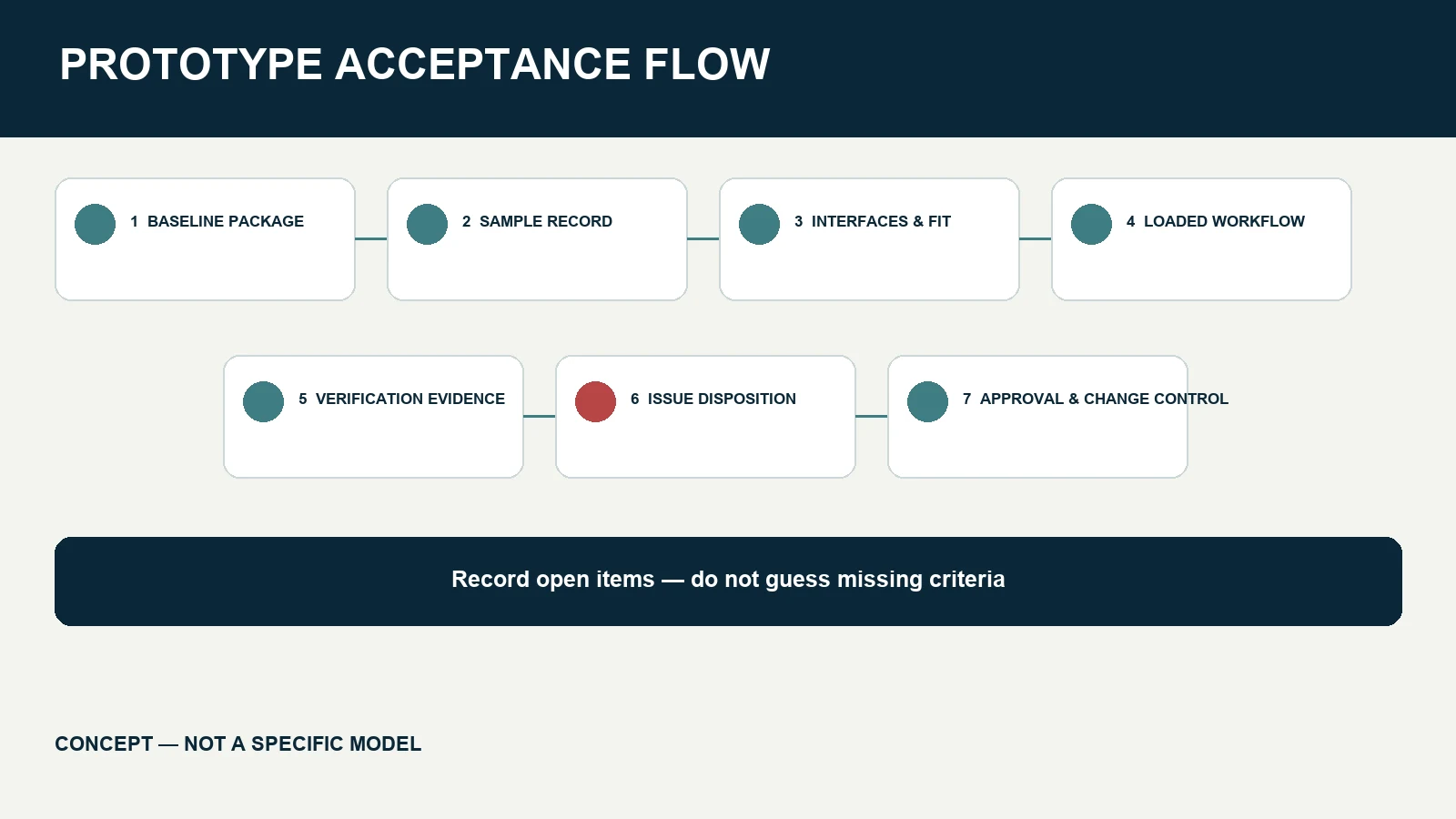
Use a structured prototype acceptance process
1. Pre-review document check
Confirm that the baseline package and deviation list are available. Postpone decisions that depend on missing device information rather than asking reviewers to guess.
2. Incoming sample record
Assign a sample identifier. Photograph the received condition and record the sample’s build date, configuration and known non-production parts.
3. Dimensional and interface review
Compare critical interfaces and envelopes with controlled drawings using methods defined by the responsible quality or engineering team.
4. Assembly and workflow review
Install the specified equipment and accessories. Review transport, positioning, operation, cleaning access and service sequences under representative conditions.
5. Verification review
Match required structural, stability, movement, braking, electrical, packaging or other verification activities to their responsible owners. Distinguish tests completed on this exact configuration from tests planned or inherited from another design.
6. Issue disposition
For each issue, record its evidence, owner, proposed action and affected documents. Classify whether the sample must be rebuilt, a drawing must change, or more evidence is required.
7. Approval and change control
Approval should identify exactly what was accepted and what remains open. A later change to the device, mounting position, base, caster, accessory, cable, finish or production method may trigger partial or full reassessment.
What to send in a prototype RFQ
Give the cart manufacturer enough information to plan the sample rather than merely price a shape:
- device drawings and installation instructions;
- device and accessory schedule;
- approved mass and load-position inputs;
- target cart envelope and mounting interfaces;
- tray, column, handle and cable requirements;
- preferred three-, four- or five-caster concept;
- workflow, floor and space constraints;
- target-market and documentation requirements;
- expected prototype maturity and quantity; and
- acceptance, change-control and packaging expectations.
Ask which inputs remain unresolved, which components are production intent and which verification activities are excluded from the quotation.
CRF catalog references
The CRF Aluminum Alloy Medical Monitor Cart can serve as a four-caster catalog reference for a monitor-cart discussion. The CRF 5-Caster Silent Laryngoscope Medical Cart provides a distinct five-caster reference. These pages do not prove compatibility, prototype acceptance, current stock or an advantage of one base over another.
Review the CRF medical cart collection and identify the closest structural starting point, then submit your own equipment and acceptance inputs for project-specific evaluation.
Limits of this checklist
This article does not state CRF alloy grades, load capacities, validated tests, certifications, tolerances, prices, inventory or lead times. It does not establish that a custom cart is a cleared or approved medical device. The finished-system manufacturer and qualified teams must determine applicable standards, regulatory classification, risk controls and evidence for the intended market and use.
FAQ
Is a good-looking prototype ready for production?
No. Appearance does not establish drawing conformance, equipment compatibility, structural performance, repeatable assembly or completed verification.
Can a component test be applied to the entire cart?
Not automatically. Confirm whether the evidence applies to the same component, installation, load and complete configuration. Document any rationale used by qualified reviewers.
Must every prototype use final production parts?
That depends on the prototype stage, but simulated or temporary parts must be clearly identified. A production-intent acceptance decision should not hide non-production substitutions.
Does five-caster prototype acceptance prove superiority over four casters?
No. Acceptance applies to the reviewed configuration and criteria. Wheel count alone does not determine stability, maneuverability or suitability.
Request a project-specific prototype review
Browse CRF’s aluminum medical equipment cart references and send an RFQ through the contact page or a relevant product page, or email sales@szcrftech.com. Include your controlled device package, accessory list, base concept, expected prototype stage and acceptance plan. Ask CRF to return a scope that identifies deliverables, exclusions and open inputs before sample work begins.