
Primary keyword: starlink pipe mount
Secondary keywords: starlink pole mount; starlink pole mount adapter; Starlink Gen 3 pipe mount; Starlink Standard pipe adapter
Intent: Commercial investigation / product fitment
Funnel: Consideration / decision
Business value: Medium
Difficulty: KD 14 for “starlink pipe mount,” KD 28 for “starlink pole mount,” and KD 31 for “starlink pole mount adapter” in the local library.
Keyword source: Semrush via seotools8 (US database): “starlink pipe mount” volume 390/KD 14/CPC USD 0.53; “starlink pole mount” 2,900/KD 28/CPC USD 0.50; “starlink pole mount adapter” 590/KD 31/CPC USD 0.48. Fresh GSC through 2026-10-04 discloses no exact-topic query, so these platform metrics and verified catalog evidence—not current CRF traffic—drive selection.
SEO title: Starlink Pipe Mount vs Pole Adapter Fitment Guide | CRF
Slug: /starlink-pipe-mount-vs-pole-adapter/
Meta description: Compare Starlink pipe-clamp mounts and pole adapters by terminal generation, tube geometry, interface, cable route, environment, retention and sample fit.
H1: Starlink Pipe Mount vs Pole Adapter: A B2B Fitment Guide
A Starlink pipe mount and a Starlink pole adapter solve different interface problems. A pipe-clamp mount fastens around a suitable tube and supports a terminal platform or adapter assembly; a pole adapter typically connects the terminal interface to the top or end of a compatible mast. Select by exact terminal generation, tube geometry, mounting direction, cable route, environment and verified fit—not by the words “pipe” and “pole” alone.
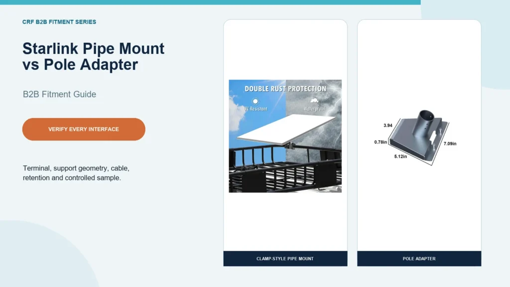
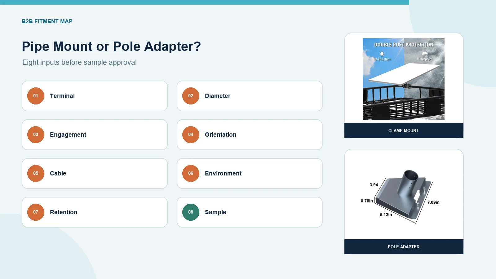
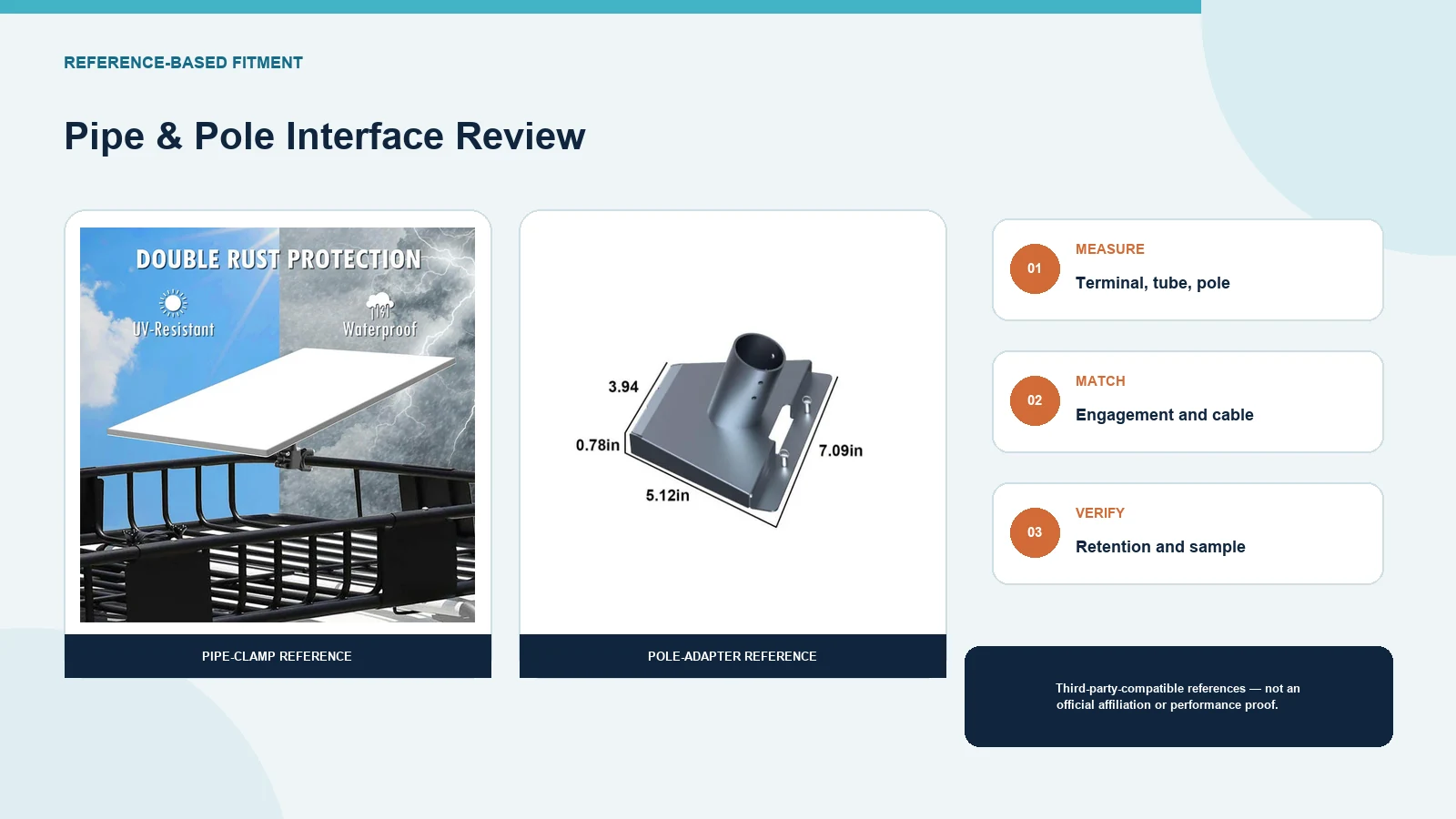
CRF’s live catalog provides two distinct third-party-compatible examples. Product 4802 is an aluminum-alloy clamp-style bracket presented for a compatible Starlink Standard Gen 3 terminal on suitable round tubes. Product 4807 is a screw-fixed metal pipe adapter presented for a compatible Starlink Standard Gen 3 terminal and a suitable pole. These products are not official Starlink products, and compatibility must be checked against the terminal and installation.
First Confirm the Exact Terminal
“Starlink” is not a complete interface specification. Before comparing mounts, record:
- terminal family and generation;
- actuated or non-actuated form where relevant;
- terminal interface dimensions;
- required orientation;
- cable connector and exit path;
- any official adapter already owned; and
- destination market and installation type.
Do not assume that a mount labeled for Standard, Mini, an earlier generation or another terminal family is interchangeable. Use the terminal owner’s current documentation and physically verify the interface.
What Is a Clamp-Style Starlink Pipe Mount?
A clamp-style pipe mount wraps around or fastens to a tube. It may be useful where an existing round member—such as selected rack tubing or a fixed pipe—is the structural attachment point.
CRF Product 4802 shows this architecture: a split clamp, adjustable connection and terminal support platform. Its live product page lists a rod-diameter range of 0.8–1.7 inches (approximately 20.3–43.2 mm) from supplier data, but a buyer should confirm the current drawing and sample before ordering.
Inputs to check
- tube outside diameter and tolerance;
- roundness, coating and surface condition;
- tube wall thickness and structural support;
- clamp width and available straight length;
- nearby joints, welds and obstructions;
- fastener access and tool clearance;
- terminal orientation and adjustment limits;
- cable clearance through every position; and
- secondary retention required by the application.
A diameter match alone does not establish structural suitability.
What Is a Starlink Pole Mount Adapter?
A pole adapter connects a compatible terminal interface to a mast or pole socket. Depending on the design, it may slide over, into or around the pole and use screws or other retention.
CRF Product 4807 shows a terminal interface plate with an inclined socket and multiple locking screws. Supplier imagery on the live page lists a 40 mm pipe interface, but the page also records conflicting overall dimensions from source graphics. Final socket diameter, insertion depth, hole spacing, fasteners and material must therefore be confirmed against a controlled drawing or sample.
Inputs to check
- pole outside diameter and tolerance;
- insertion or overlap length;
- pole material, wall thickness and condition;
- adapter socket geometry;
- fastener type, engagement and access;
- gasket or liner placement;
- cable route through or around the adapter;
- orientation and rotation control; and
- inspection access after installation.
Side-by-Side Selection Table
| Decision point | Clamp-style pipe mount | Pole adapter |
|---|---|---|
| Structural attachment | Around a suitable tube | At the end or top interface of a suitable pole |
| Key dimension | Tube outside diameter and clamp range | Pole diameter, socket fit and insertion depth |
| Space requirement | Straight tube length and clamp/tool access | Clear pole end and adapter/tool access |
| Orientation control | Clamp and adjustable-joint geometry | Socket, screws and adapter geometry |
| Cable review | Around clamp, joint and platform | Through or around socket and terminal interface |
| Typical procurement risk | Diameter fits but tube or clamp engagement is unsuitable | Socket appears compatible but insertion, screws or cable path conflict |
| Required validation | Controlled drawing plus representative tube and terminal | Controlled drawing plus representative pole and terminal |
Neither architecture is universally stronger, safer or more weather-resistant. Those outcomes require configuration-specific engineering and evidence.
Measure the Tube or Pole Correctly
Provide a drawing or measurement sheet rather than a nominal label.
Diameter and tolerance
Measure the actual outside diameter at several points. Paint, powder coating, corrosion, ovality and seams can affect fit.
Wall and support
Record material, wall thickness, unsupported length, joints and the structure that carries the pole or tube. The mount supplier cannot infer structural capacity from diameter alone.
Available engagement
Mark the straight, unobstructed length for a clamp or socket. Include weld beads, curves, rack joints, caps and nearby hardware.
Installation access
Confirm that tools can reach every fastener and that inspection remains possible after the terminal is installed.
Preserve Terminal Orientation and Sky View
Follow the official instructions for the exact terminal and service. Official Starlink installation guidance emphasizes selecting a location with a clear view of the sky and using the app’s obstruction and alignment tools where applicable. A compatible bracket should not be treated as a substitute for those instructions.
The buyer or qualified installer should confirm:
- the terminal’s permitted orientation;
- clear view of the sky at the site;
- absence of uncontrolled obstruction from racks, walls or equipment;
- adjustment and locking sequence;
- final alignment process; and
- access for future inspection.
CRF does not claim that a third-party bracket changes network coverage or terminal performance.
Plan the Cable Route Before Tightening the Mount
Cable routing is part of fitment, not a final cosmetic step. Map:
- the terminal connector;
- route through or around the support interface;
- retention points;
- drip or service loops where required by the approved installation plan;
- bend guidance from the cable owner;
- abrasion and pinch points;
- transition into the building, vehicle or equipment space; and
- disconnect and maintenance access.
Keep the cable away from clamp gaps, rotating joints, sharp edges, hot surfaces and uncontrolled movement. Do not use the connector as strain relief.
Distinguish Fixed and Dynamic Applications
A stationary building installation, a parked portable setup and a moving vehicle are not equivalent.
Fixed installation
Review structural attachment, weather exposure, access, grounding or bonding obligations where applicable, cable entry and periodic inspection.
Portable setup
Define assembly, leveling, anchoring, exclusion zones, cable protection and storage. Portability does not establish wind resistance.
Vehicle, RV, marine or other dynamic use
Vibration, shock, speed, repeated clamp loading and secondary restraint require application-specific review and testing. CRF’s catalog imagery does not establish a road-speed, wind-speed, marine, corrosion or vibration rating.
Environmental and Material Questions
Ask for evidence relevant to the destination environment:
- actual base material and grade;
- coating or surface-treatment specification;
- fastener material and finish;
- galvanic interaction between mount, pole and fasteners;
- water-drainage and crevice details;
- UV, corrosion or salt exposure requirements;
- temperature range; and
- inspection and replacement criteria.
A black coating or a “weatherproof” marketing phrase is not test evidence. Product 4807’s source title says stainless steel while its attribute table says only metal; confirm grade and finish in the quotation.
Retention and Fastener Control
The installation plan should state:
- every required fastener and washer;
- tightening method and any specified torque from the approved instructions;
- thread-locking or locking feature, if engineering requires it;
- insertion and engagement witness marks;
- secondary retention method, where required;
- installer qualification;
- post-installation inspection; and
- reinspection interval.
Do not invent torque values or reuse values from another mount. Obtain them from the controlled product instructions or responsible engineering authority.
Sample Fitment Plan
Use the exact terminal and representative tube or pole where possible.
Identity
- Terminal family and generation match the purchase specification.
- Mount model and revision match the drawing.
- Included hardware matches the BOM.
Mechanical fit
- Clamp or socket fits the measured structure.
- Required engagement is achieved without uncontrolled gaps or interference.
- Terminal interface seats and retains as designed.
- Tools can access all fasteners.
Orientation and cable
- Approved orientation can be reached and locked.
- Cable connects without strain.
- Route avoids pinch, abrasion and moving interfaces.
Site and service
- Sky-view and alignment checks follow current official instructions.
- Inspection and removal remain possible.
- Deviations are documented and approved before release.
Sample fit confirms only the tested configuration and does not establish structural, wind, road or environmental performance without the relevant method and evidence.
RFQ Checklist
Send CRF:
- Exact Starlink terminal family and generation.
- Terminal interface photos and drawings.
- Pipe or pole outside diameter, tolerance and wall information.
- Available straight length and installation geometry.
- Fixed, portable or dynamic application description.
- Mounting orientation and adjustment requirements.
- Cable route and connector-clearance requirements.
- Environment, material and finish requirements.
- Retention, inspection and evidence requirements.
- Required included hardware and packaging.
- Sample quantity and fitment acceptance method.
- Order quantity and destination.
Common Fitment Mistakes
Buying by “Gen 3” wording alone
Terminal family, interface and mounting architecture still need verification. Similar names do not prove interchangeability.
Checking only diameter
Diameter does not define wall strength, insertion length, clamp engagement, access or structural support.
Planning the cable after mounting
The cable may conflict with the adapter, fasteners or structure. Freeze the route before sample approval.
Treating vehicle imagery as dynamic-use evidence
A photograph on an RV or rack does not establish speed, vibration, wind or retention performance.
Assuming a third-party mount is official
The referenced CRF products are presented as third-party compatible accessories, not official Starlink products.
FAQ
Is a Starlink pipe mount the same as a pole adapter?
No. A clamp-style pipe mount generally attaches around a tube, while a pole adapter connects the terminal interface to a compatible mast or pole socket. Verify the actual geometry.
What measurements are needed for a Starlink pole mount?
Provide exact terminal version, pole outside diameter, wall and material, insertion or clamping length, nearby obstructions, orientation, cable route and installation environment.
Can the CRF clamp mount fit every Gen 3 terminal?
No universal compatibility is claimed. Product 4802 is presented for a compatible Starlink Standard Gen 3 terminal, subject to drawing and physical verification.
Is the 40 mm adapter dimension guaranteed for Product 4807?
The live product evidence lists a 40 mm interface from supplier imagery, but final dimensions must be confirmed against the current drawing or sample before ordering.
Can these mounts be used on a moving vehicle?
Only after application-specific engineering, retention and testing. No road-speed, wind-speed or vibration rating is claimed here.
Request a Starlink Mount Fitment Review
Send CRF the exact terminal version, tube or pole drawing, installation geometry, cable route, environment and sample criteria. CRF can compare a clamp-style pipe mount with a pole-adapter direction and prepare a configuration-specific quotation. Request a fitment-specific RFQ.
Internal links
- View the verified CRF Starlink Gen 3 pipe-clamp mount
- View the verified CRF Starlink Standard Gen 3 pipe adapter
- Browse CRF Starlink mounts
CTA: Request a Quote — include the terminal version, tube/pole drawing, cable route and fitment acceptance plan.
Editorial limitations: B2B fitment education only. Starlink is a third-party trademark. CRF does not claim official affiliation, universal compatibility, structural capacity, wind or road-speed rating, corrosion performance, certification, price, stock, MOQ or lead time.