
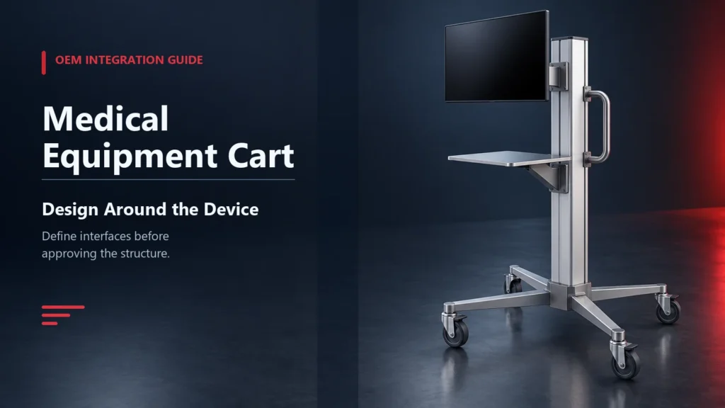
A medical equipment cart should be engineered around the installed device, its users and its real travel route. For an OEM integration project, buyers need to define the equipment envelope, mass, center of gravity, mounting interface, cables, power components, accessories, cleaning process and target market before approving the cart structure. A cart chosen by appearance alone can create fit, stability, service or packaging problems later.
CRF supports customized cart projects in aluminum alloy and stainless steel through requirement review, structural development, metal processing and assembly. The appropriate architecture and verification plan must be agreed for each finished configuration; customization does not automatically establish medical-device compliance.
Buyer takeaway: Send a device interface pack with the RFQ: 2D/3D envelope, mass, center-of-gravity information when available, mounting points, connector locations, cable paths, service clearances and accessory list.
What Is a Medical Equipment Cart?
A medical equipment cart is a mobile support system designed to carry, position or integrate equipment and related accessories. Depending on the project, it may include a base, vertical column, equipment shelf, monitor mount, work surface, handle, storage, cable management, power-component space and braking casters.
Common project directions include carts for ultrasound, ECG, patient monitoring, endoscopy support, computers, displays and other mobile equipment workflows. CRF’s current medical cart catalog contains products across these directions, but a new OEM cart still requires its own confirmed interface and specification.[1]
Medical Equipment Cart vs Medical Supply Cart
| Area | Equipment cart | Supply cart |
|---|---|---|
| Main design driver | Installed device and interfaces | Stored-item list and retrieval sequence |
| Core technical inputs | Envelope, mass, center of gravity, mounts and cables | Usable drawer sizes, dividers, bins and access map |
| Structure | Platform, column, mount or equipment enclosure | Shelves, drawers or cabinet body |
| Stability review | Device and accessory positions | Drawer, shelf and accessory positions |
| Service access | Device connectors, ventilation, cables and removable panels | Locks, slides, organizers and replaceable hardware |
| Procurement document | Device integration pack | Drawer-by-drawer content map |
Hybrid carts need both sets of inputs. Do not omit the storage map simply because a monitor or computer is installed.
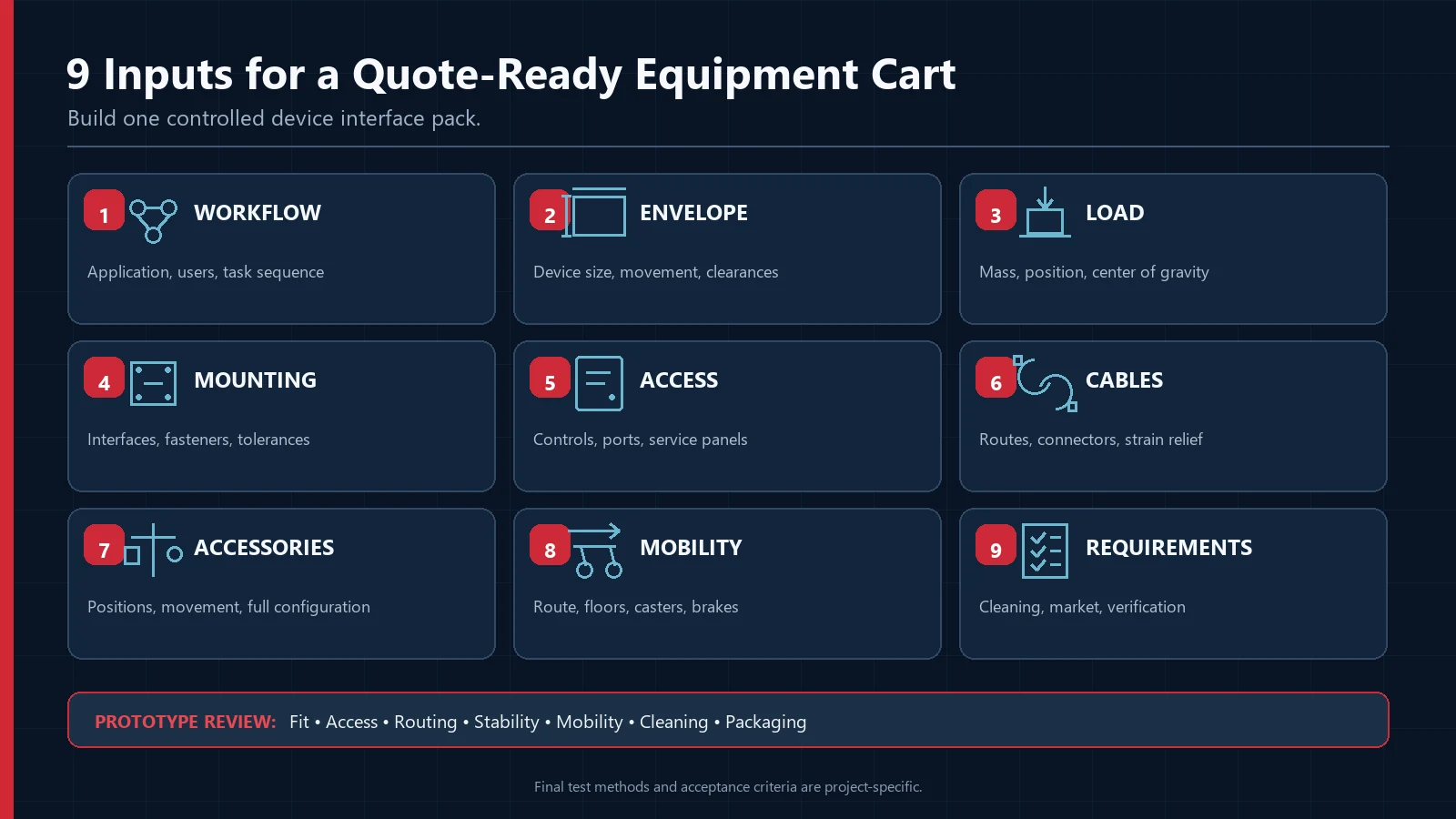
Nine Inputs for a Quote-Ready Equipment Cart
1. Intended application and user workflow
Describe the task rather than naming only the equipment. State where the cart is prepared, how it reaches the use area, what users adjust, which controls they access and where it is stored. Identify the operating and transport configurations if components move or fold.
2. Equipment envelope
Provide maximum width, depth and height, including connectors, protrusions and required clearances. A product outline should distinguish fixed geometry from doors, lids, controls, vents and service panels that need room to operate.
If several device variants will share one platform, provide the complete dimensional range and identify the worst-case combination.
3. Mass and load position
State the mass of the device, batteries, adapters, drawers, accessories and expected supplies. Provide center-of-gravity information when available. A load mounted high or outside the base footprint influences the cart differently from the same mass placed low and centrally.
Define normal use, transport and service positions. The final verification plan should address the approved load combinations and positions rather than only the empty frame.
4. Mounting and retention interface
Supply hole patterns, fastener requirements, contact surfaces, permitted clamping zones and installation tolerances. Clarify whether the device must be removable and what tools or authorization are required.
Avoid designing from a photograph. A similar enclosure can have different mounting points, structural zones or access restrictions. When drawings cannot be shared, discuss a controlled physical sample or interface fixture.
5. Controls, ports and service clearances
Map controls, displays, connectors, consumables, ventilation openings and maintenance panels. Define which must remain visible or reachable during use. Record cable bend space and connector insertion/removal direction.
A cart should not obstruct airflow, trap a service panel or make routine connection work dependent on disassembling unrelated parts.
6. Cable and power-component management
List every cable, its endpoints, connector size, minimum practical bend requirement and whether it moves during adjustment. Identify power supplies, batteries, strips or adapters that need mounting, ventilation or replacement access.
Cable routing should avoid pinch points, sharp edges, caster paths and user handles. Specify strain relief, separation, service loops and removable covers as project requirements—not as assumptions. Electrical integration and applicable safety verification must be defined by qualified project personnel.
7. User adjustment and accessory positions
Describe height, tilt, rotation, shelf or arm movement only where the application requires it. State operating ranges, user contact points and locked transport positions. List every accessory and its location, including displays, scanners, keyboards, handles, baskets or holders.
Accessories can change reach, total envelope and stability. Include all intended combinations before structural approval.
8. Mobility and environment
Provide the travel route, floor materials, thresholds, gaps, ramps, elevators, doorway limits, turning space and storage bay. Define caster behavior, brakes, directional control, bumper needs and noise expectations.
Evaluate the configured system over the intended route. A caster selected for an empty prototype may behave differently after equipment and accessories are installed.
9. Cleaning, finish and target-market requirements
List cleaning products, dilution practice, application method, contact time and frequency when known. Review exposed surfaces, seams, fasteners, labels, cable covers, handles, shelves and caster housings.
CDC guidance notes that a compatible cleaning and disinfectant list should be included in manufacturer instructions or provided on request for noncritical patient-care equipment; compatibility can vary by chemistry and material.[2] This means the buyer should disclose the intended process and define the evidence or review needed. It does not mean any material is universally compatible.
Also identify destination countries and buyer-required standards, documents, labels and verification. Product classification and regulatory responsibility depend on intended use, supplied configuration and market.
Choosing Aluminum Alloy or Stainless Steel
Material selection should follow the complete requirement.
Aluminum-alloy direction
Often considered when frequent movement and lower frame mass are valuable, or when a fabricated column, platform and enclosure architecture supports equipment integration. Finish, joints and disclosed cleaning exposure still need review.
Stainless-steel direction
Often considered when the project favors robust shelves, cabinets or welded structures, or when moisture and cleaning exposure make a specified stainless construction relevant. Grade, finish, weld treatment, fasteners and total mass must be defined.
Neither material guarantees stability, cleanability, durability or compliance by itself. See CRF’s medical rolling cart material guide for a fuller sourcing comparison.
Build a Device Interface Pack
Use one controlled document set for supplier review:
| Input | What to provide | Why it matters |
|---|---|---|
| Device envelope | 2D/3D outline and moving zones | Prevents physical interference |
| Mass properties | Component mass and load position | Supports structural and stability review |
| Mounting | Hole pattern, fasteners and tolerances | Defines retention interface |
| Controls and ports | Location and access direction | Preserves operation and service |
| Cables | Endpoints, connector size and movement | Supports routing and strain relief |
| Power components | Size, heat/airflow and replacement access | Prevents late packaging conflicts |
| Accessories | Position and load for each configuration | Controls envelope and balance |
| Cleaning | Products and process | Supports material/finish review |
| Market requirements | Destination, documents and tests | Defines project verification scope |
Use revision numbers. If the device changes, record whether the cart interface, load case, cable route, packaging or verification must also change.
Prototype and Integration Review
A useful prototype review is evidence-based and tied to agreed acceptance criteria:
- Mechanical fit: device, mounts and accessories fit without interference.
- Retention: fasteners and interfaces match the approved drawing.
- Access: controls, ports and service panels remain reachable.
- Cable routing: no unintended pinch, abrasion, sharp-edge or caster conflict is visible.
- Configured stability: agreed load positions and adjustment states are reviewed under the project plan.
- Mobility: loaded cart travels the real or representative route.
- User interaction: handles, brakes and adjustments are reachable in intended positions.
- Cleaning access: intended surfaces and removable parts can be reached using the disclosed process.
- Service: agreed replaceable components can be accessed as planned.
- Packaging: equipment and accessories are protected in the specified shipping configuration.
The responsible engineering and compliance teams must define test methods, loads and pass/fail criteria. Prototype approval is not automatically a certification.
Design for Manufacturing and Assembly
After the interface is stable, review how the cart will be fabricated and assembled:
- reduce avoidable part variation;
- identify critical dimensions and inspection points;
- define material, finish and visible appearance expectations;
- specify fasteners, torque or retention controls where required;
- separate serviceable modules from permanent joints;
- control cable-cover and panel fit;
- plan assembly fixtures where repeatability requires them; and
- record approved substitutions and change-control rules.
CRF’s public manufacturing sequence covers structural design, metal processing, multi-station assembly, basic dimensional checks, product integration and delivery.[3] Project-specific inspection and validation remain subject to the approved requirement.
Packaging Is Part of Integration
State whether the device ships mounted to the cart, separately in the same package or through a later integration step. Define:
- assembled, partly assembled or knocked-down state;
- transport locks and moving-part restraints;
- protection for displays, columns, casters and accessories;
- carton and pallet limits;
- lifting and orientation labels;
- assembly tools and instructions;
- destination handling; and
- incoming acceptance checks.
A cart that works in the prototype room can still fail operationally if packaging allows movement, makes assembly ambiguous or separates configuration-specific parts.
OEM Medical Equipment Cart RFQ Checklist
Send these details with the inquiry:
- Application, users and workflow
- Device name/reference and controlled drawing revision
- Equipment and accessory envelopes
- Mass and center-of-gravity data when available
- Mounting interface, fasteners and tolerances
- Controls, ports, vents and service clearances
- Cable list, routes and strain-relief needs
- Power components and ventilation/access requirements
- Adjustment ranges and transport positions
- Work surface, storage and accessory list
- Normal and maximum intended loads with positions
- Overall cart envelope limits
- Travel route, floors, thresholds and turning space
- Caster, brake, handle and bumper requirements
- Aluminum-alloy or stainless-steel direction, or request for comparison
- Surface finish, color, texture and appearance criteria
- Cleaning products, method and compatibility requirements
- Target market, buyer-required documents and verification
- Prototype, pilot and forecast quantities
- Branding, labels, manuals and configuration control
- Assembly, packaging, pallet and destination requirements
- Schedule for interface freeze, prototype and delivery
Common OEM Integration Mistakes
Designing from the device’s nominal dimensions
Connectors, moving panels, service access and cable bend space can extend beyond the enclosure. Use a functional envelope.
Ignoring center of gravity
Total mass alone does not define balance. Record load position across intended configurations.
Treating cables as an assembly detail
Late cable routing can create interference, service and cleaning problems. Include cables in the interface pack.
Adding accessories after stability review
A side shelf, arm or battery can change the envelope and load case. Review complete configurations.
Making universal cleaning claims
Compatibility depends on materials, finishes and the actual cleaning product and process. Disclose and review them explicitly.
Assuming the cart inherits the device’s approvals
A new cart or integrated configuration can change the applicable assessment. Qualified parties must determine regulatory responsibility and verification for the target market.
FAQ
What information does a manufacturer need for a custom medical equipment cart?
Provide the device envelope, mass, center-of-gravity information when available, mounting interface, controls and port locations, cables, power components, accessories, workflow, route, cleaning process, quantities, destination and target-market requirements.
Can one cart platform fit several equipment models?
Possibly, if the complete dimensional, load, interface and accessory ranges are defined. Each approved configuration still needs an appropriate engineering and verification review.
Should the cart be aluminum or stainless steel?
Choose after reviewing movement, load, structure, finish, cleaning exposure and total mass. Aluminum alloy may support a lighter equipment-platform direction; stainless steel may suit robust shelf or cabinet structures. Neither is universally superior.
How should cables be specified?
List endpoints, connector sizes, movement, service loops, separation, strain relief and access. Identify pinch, abrasion and caster conflicts to avoid. Applicable electrical safety requirements must be defined by qualified personnel.
Does CRF provide custom equipment-cart manufacturing?
CRF’s verified scope includes custom cart manufacturing, structural development, metal processing and assembly in aluminum alloy and stainless steel. Exact interfaces, quantities, components and verification must be reviewed before commitment.
Is this guide medical or regulatory advice?
No. It is B2B procurement education. Clinical suitability, intended use, classification and compliance require review by the buyer’s qualified engineering, clinical and regulatory teams.
Start an OEM Cart Integration Review
Send CRF your device interface pack, application, load data, cart envelope, route, cleaning process, accessories, material direction, quantities, branding, packaging and destination. CRF can review the requirement and discuss a practical custom manufacturing approach.