

A powered medical equipment cart is not automatically the better choice. The correct architecture depends on the devices carried, simultaneous power demand, unplugged workflow, charging opportunities, service model, destination market and the party responsible for electrical-system compliance. A non-powered aluminum cart can be simpler and lighter when each device has its own battery or the cart only provides mechanical support. Integrated or add-on power may fit workflows that require several devices to remain available away from wall outlets, but it adds mass, heat, wiring, charging, documentation and maintenance considerations.
CRF’s core business is custom aluminum alloy medical equipment carts with three-, four- and five-caster bases. This guide helps B2B buyers prepare requirements for a mechanical cart and any separately qualified power integration. It does not state that every CRF cart includes a battery or power system. It is procurement education, not medical, electrical-safety or regulatory advice. The responsible engineering and regulatory teams must define and verify the finished system.
Begin with the workflow, not the battery
Before choosing an architecture, map one representative work cycle:
- Where does the cart start and finish?
- Which devices operate, charge or remain idle at each stage?
- How long must the cart work unplugged?
- Is the cart plugged in during use, during breaks or only at a charging area?
- Can a device battery or removable battery be exchanged without disrupting the workflow?
- Who connects, inspects, cleans and services the power components?
- What happens when power is unavailable or the battery reaches its replacement threshold?
Commercial medical-cart systems demonstrate several valid approaches, including non-powered frames, onboard charging and removable-battery systems. Those examples show that architecture follows workflow; they do not establish suitability for a different device or CRF project.
Compare three practical architectures
| Architecture | What the cart provides | Questions for the buyer | Integration consequences |
|---|---|---|---|
| Non-powered mechanical cart | Structure, mobility, mounts, trays and cable routing | Do devices have adequate independent power? Where are adapters stored? | Usually fewer cart-level electrical parts, but device charging and loose adapters still need a plan |
| Cart with add-on power module | Mechanical cart plus an approved external or mounted power subsystem | Is the module compatible with every device and intended market? Who owns installation and validation? | Requires controlled mounting, cable routes, ventilation, access and change review |
| Fully integrated powered cart | Battery, charger, distribution, controls and enclosure integrated into the cart system | What are the loads, duty cycle, interfaces, alarms, charging method and compliance responsibilities? | Highest integration effort; affects mass distribution, thermal management, service and documentation |
“Powered” is not a complete RFQ specification. Buyers must identify the actual devices, adapters, connectors, power states and responsible integrator.
Build a controlled power inventory
List every load and operating state
Provide manufacturer-controlled information for the monitor, computer, printer, scanner and other approved equipment. Record each device’s input requirements and whether it operates, starts up or charges at the same time. Do not estimate a power budget from generic online values.
The responsible electrical engineer should calculate the project-specific demand, charging reserve and any startup behavior. CRF should receive only approved inputs needed to package the selected components and review their mechanical effects.
Define charging and cable states
Show where the mains cord, adapters and excess cable are stored during transport. Define plug-in and unplug sequences, connector access, strain relief and the location of user indicators. A cable route that works while parked may snag, bend or obstruct a handle, caster or pedal during movement.
Assign ownership
The RFQ should name who selects the battery, charger, power supply, distribution hardware and protective devices; who assesses applicable standards; who supplies labels and instructions; and who validates the finished assembly. A cart fabricator’s ability to create a bracket or enclosure does not by itself qualify the electrical subsystem.
Review mechanical effects of the power system
Mass and center of gravity
Battery, charger, isolation component, power strip, computer and cable bundle all change the loaded configuration. Provide approved masses and mounting positions so the base, column, fasteners and caster arrangement can be reviewed together. Do not assume that a five-caster base is inherently more stable than a three- or four-caster design. Equipment weight, center of gravity, base dimensions, caster layout, brakes, accessories and validation all matter.
Ventilation and access
Do not place a heat-producing component in a sealed compartment unless the qualified design explicitly supports it. Define required clearances, airflow, inspection access and cleaning access from the selected component documentation. Service staff should be able to reach replaceable parts without dismantling unrelated safety-critical interfaces.
Enclosure and mounting
Specify the approved component outline, connector direction, retention method and removal path. The design should prevent routine movement from turning a power module into a loose load while avoiding unsupported claims about impact or vibration performance.
User interface
Indicators, switches, charging connectors and cord hooks must remain visible and reachable in the approved layout. Confirm that controls are not confused with cart height, brake or device controls. Label content belongs in the controlled documentation set.
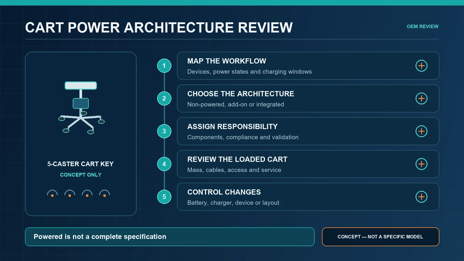
Powered-cart OEM design review sequence
1. Freeze intended use and device configuration
Identify the supported equipment, accessories, users, route and operating states. Mark optional configurations separately rather than combining them into an impossible “maximum” cart.
2. Select the architecture and responsible suppliers
Decide whether power remains within each device, uses an approved add-on module or becomes an integrated subsystem. Record supplier references and the party responsible for compatibility and compliance.
3. Release mechanical interface data
Provide component drawings, approved masses, mounting holes, connector envelopes, cable bend and access requirements, and any ventilation instructions from authoritative sources.
4. Review the loaded cart
Assess the base, column, handles, casters, brakes, trays, cables and power components as one representative configuration. Include movement, parking, connection, cleaning and service states.
5. Evaluate a representative sample
The project team should define observable acceptance criteria before the review. Document installation, cable routing, connector access, charging workflow, thermal observations and unresolved issues. Electrical and regulatory verification must be performed by qualified parties under the project’s applicable requirements.
6. Control later changes
A substituted battery, charger, adapter, cable, enclosure, device or mounting position can change the finished system. Route changes through documented engineering review rather than informal purchasing substitution.
RFQ checklist for a powered medical equipment cart project
Send the cart manufacturer:
- intended use and destination markets;
- device and accessory list with controlled drawings;
- approved mass and center-of-gravity inputs;
- device power-input information from responsible sources;
- simultaneous operating and charging states;
- required unplugged workflow and charging locations;
- selected power architecture and responsible electrical integrator;
- battery, charger, adapter and distribution references, if already selected;
- cable, connector, indicator, ventilation and service-access requirements;
- preferred three-, four- or five-caster concept, if any;
- route, floor, threshold and parking conditions;
- cleaning method and approved agents supplied by the responsible team;
- labeling, documentation and change-control requirements; and
- sample-review plan with acceptance ownership.
Ask suppliers to state exclusions and open inputs. A quotation should distinguish the mechanical cart, buyer-supplied equipment and any power components included in the offered scope.
CRF references for discussion
The CRF 4-Wheel Universal Ultrasound/ECG Medical Cart is an aluminum equipment-support reference whose page requires device-specific review of dimensions, mounting, weight and cable routing. The CRF Five-Wheel Medical Monitor Cart is a separate monitor-cart reference. Neither listing proves compatibility with a proposed power system.
Browse the CRF medical cart collection to choose a mechanical starting point, then confirm every included component in the approved drawing and quotation.
Limits of this guide
This article provides no runtime, battery chemistry recommendation, capacity, voltage, load rating, temperature limit, leakage-current result, EMC result, certification, medical outcome, price, stock or delivery claim. Standards and regulatory obligations depend on the finished system, intended use and destination market. Use qualified electrical, safety and regulatory professionals.
FAQ
Is a powered medical equipment cart always better than a non-powered cart?
No. A powered design can support devices away from outlets, but it adds integration and lifecycle requirements. A non-powered cart may suit devices with their own qualified batteries or workflows that need only mechanical support.
Can CRF add a battery enclosure to an aluminum cart?
CRF can review custom mechanical requirements, but feasibility, included scope and responsibility must be confirmed for the specific project. The buyer should supply approved component data and identify the qualified party responsible for electrical integration and validation.
Does a five-caster base make a powered cart stable?
Not by itself. The full loaded configuration—including component masses, center of gravity, base geometry, caster layout, brakes and accessories—requires project-specific review and verification.
What should be frozen before prototype production?
Freeze the intended device set, power architecture, component references, mounting and cable interfaces, loaded configuration, responsible parties, documentation set and sample acceptance plan.
Discuss a custom cart architecture with CRF
Explore CRF’s aluminum medical equipment carts and send an RFQ through the contact page or relevant product page, or email sales@szcrftech.com. Include the equipment drawings, approved mass inputs, power architecture, component responsibilities, cable and service requirements, workflow and preferred base concept. CRF can review the mechanical cart scope and identify open inputs before a drawing and prototype plan are agreed.