
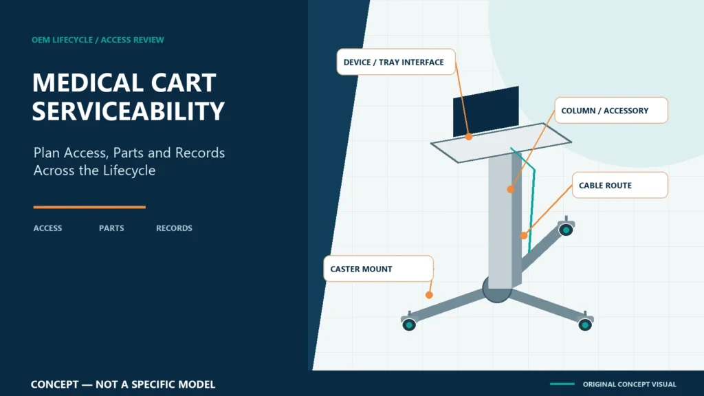
An aluminum medical equipment cart should be specified for inspection, cleaning, adjustment and authorized replacement throughout its intended project life—not only for first-day fit. Buyers should define access to fasteners and cables, identify wear and replacement items, control drawings and part revisions, assign maintenance responsibilities, and decide which configuration changes require renewed engineering or finished-system review.
CRF focuses on aluminum alloy medical equipment carts with three-, four- and five-caster bases. This article addresses equipment-support carts, not walking aids. It provides B2B procurement education and does not establish medical-device servicing instructions, regulatory status or a maintenance schedule for any finished system.
Serviceability begins in the OEM brief
When a device, monitor, tray, battery, power component or accessory is installed on a cart, access can change. A fastener that is visible on an empty column may become blocked. A cable service loop may be trapped behind a bracket. A caster may be replaceable in theory but difficult to identify or reach in the finished assembly.
Include lifecycle questions before approving the layout:
- Who inspects the cart and installed equipment?
- Which activities are permitted, and which require qualified personnel?
- What must be removed to reach a fastener, cable or caster?
- Which settings or interfaces must be recorded before disassembly?
- Which parts are expected to be replaceable?
- How will the exact approved part and revision be identified?
- What evidence is required after reassembly?
The FDA distinguishes servicing from remanufacturing for finished medical devices based on the activity performed and whether it significantly changes performance or safety specifications or intended use. A cart buyer should not infer a regulatory conclusion from this article. The responsible finished-device organization must determine applicable obligations.
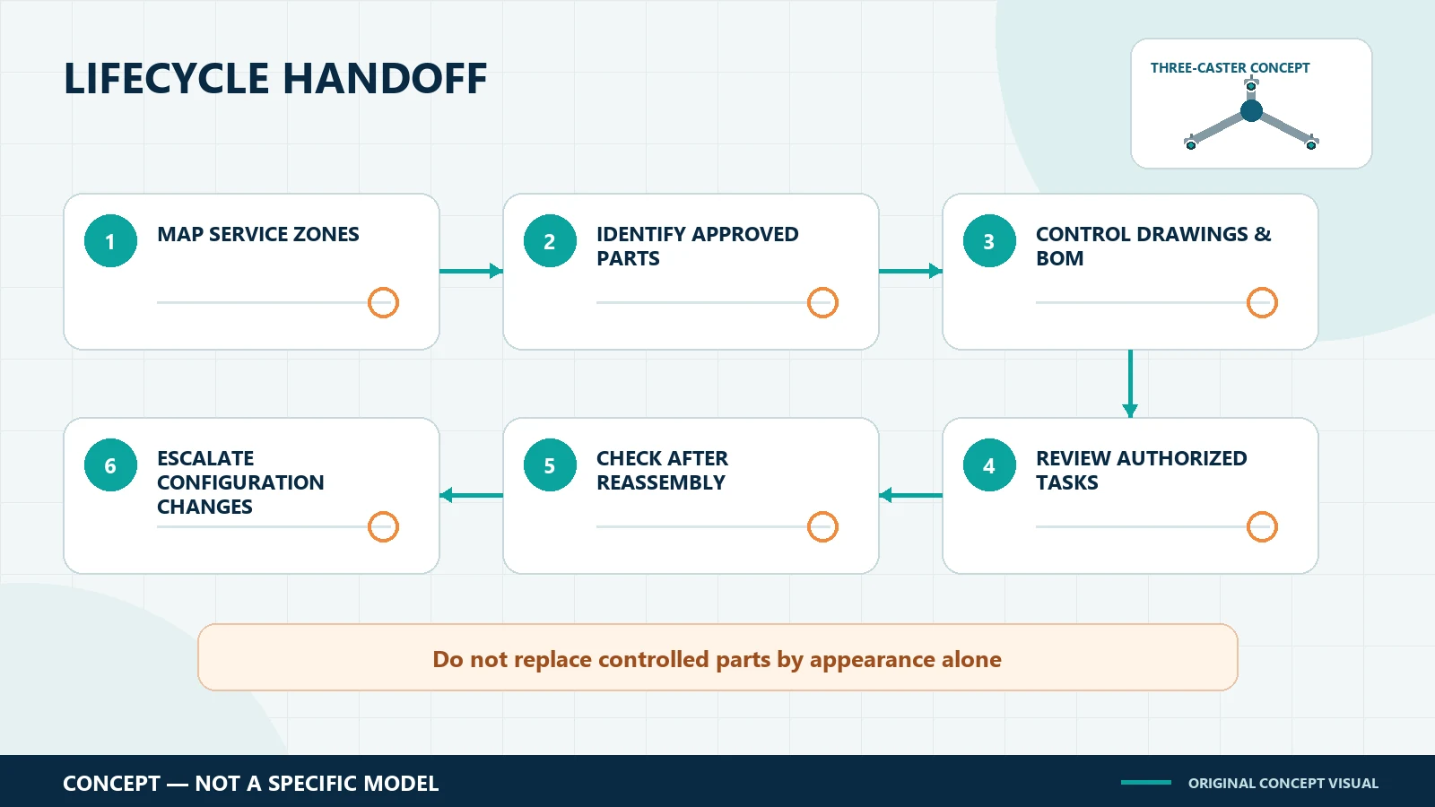
Map the service zones
Device and tray interface
Review access to attachment fasteners, anti-rotation features, adjustment points and any secondary retention. Confirm that inspection does not require uncontrolled movement of the mounted device. Device removal and reinstallation steps should come from approved project documentation.
Column and accessory interfaces
Record how trays, handles, baskets and other accessories attach to the column. Define permitted positions and the sequence for adjustment. If an accessory can change load position or obstruct another component, the approved configuration should be controlled.
Cable route and connectors
Service access is not the same as an open cable bundle. Cables may need retention, bend clearance, strain management, separation or protected routing depending on the finished system. Identify connection points, access panels, service loops and the approved reassembly route. Electrical work belongs within the responsible organization’s defined scope.
Base and casters
Caster access should be reviewed with base covers, counterweights and nearby cable paths in place. Record the mounting interface, orientation, control function and approved part identifier. A replacement that fits physically may not reproduce the original offset, tread, swivel, brake or directional behavior.
Labels and configuration records
Decide where cart, assembly and component identifiers will be visible. The service record should be able to connect the physical configuration to the approved drawing, BOM and relevant instructions without relying on memory.
Build a lifecycle documentation pack
A useful handoff may include the following project-controlled items, where applicable:
| Record | Procurement purpose |
|---|---|
| Approved general arrangement | Shows the accepted device, tray, column, base and accessory layout |
| Interface drawings | Controls mounting holes, fasteners, clearances and attachment details |
| BOM or approved-parts list | Identifies configuration-specific components and revisions |
| Cable-routing record | Shows retention points, service loops and connector access |
| Caster specification | Identifies mount, wheel, swivel and brake functions |
| Assembly instructions | Defines controlled installation and adjustment steps |
| Inspection criteria | States what is checked, by whom and with what evidence |
| Change record | Links substitutions or layout changes to review and approval |
The exact pack depends on contract scope. Do not request generic certificates as a substitute for configuration-specific documents.
Distinguish maintenance from redesign
Routine inspection or like-for-like replacement is not the same as moving equipment, changing a base, adding accessories or substituting a caster. A change may affect load distribution, cable reach, access, maneuvering, braking, cleaning or packaging.
Create an escalation rule. Re-review may be needed when changing:
- installed device or bracket;
- equipment height or position;
- tray dimensions or accessory location;
- cable type or routing;
- caster model, mount, offset, tread or control function;
- base geometry or counterweight;
- handle position;
- fastener or material specification; or
- any part tied to a validated finished-system requirement.
This does not mean every change has the same risk. It means changes should be assessed by qualified responsible parties rather than accepted because they look minor.
Review three-, four- and five-caster bases correctly
Base service access differs by geometry, but wheel count alone does not determine maintainability or performance. Inspect the actual arrangement for fastener access, caster removal path, base-cover removal, control-pedal clearance and safe support during authorized maintenance.
Also account for equipment weight, center of gravity, base dimensions, caster layout, brakes, attachments and the approved service state. A five-caster base is not inherently more serviceable or stable than a three- or four-caster base. Each complete configuration requires review.
Prototype serviceability review
1. Freeze the sample configuration
Record device, bracket, trays, cables, accessories, base, casters and document revisions. Do not review a simplified sample without identifying the differences.
2. Walk through authorized tasks
Use the proposed inspection, adjustment and replacement sequence. Observe blocked tools, hidden fasteners, pinched cables, ambiguous labels and components that require unnecessary disassembly.
3. Reassemble to controlled documents
Verify that the cart can be returned to the approved configuration. Record torque or other criteria only when supplied and approved by the responsible engineering team; this guide invents none.
4. Review after reassembly
Define the inspections or functional checks required after the task. Criteria may involve interfaces, cable routing, controls, casters, brakes or the complete finished system, depending on scope.
5. Close documentation gaps
Resolve mismatches among drawing, BOM, physical sample and instructions before approval. Record open items instead of filling gaps with assumptions.
OEM RFQ checklist
Provide:
- device and accessory drawings;
- approved or proposed equipment layout;
- responsible parties for installation, inspection and maintenance;
- required access zones and permitted tools;
- cable and connector service requirements;
- expected replaceable items and identification method;
- preferred three-, four- or five-caster concept;
- cleaning-access requirements;
- document, revision and change-control expectations; and
- prototype serviceability review and handoff criteria.
Ask what is included in the supplier’s scope and what remains the buyer’s or finished-device organization’s responsibility.
CRF references for project discussion
The CRF Aluminum Alloy Medical Monitor Cart is a catalog reference for an equipment-support discussion. The CRF 5-Caster Silent Laryngoscope Medical Cart is a separate five-caster reference. Their pages do not establish service instructions, compatibility, replacement-part availability or acceptance for another project.
Use the CRF medical cart collection to identify a starting platform, then confirm lifecycle documentation and service access in the quotation, drawing and sample scope.
Limits of this guide
This article does not provide a maintenance interval, service manual, repair authorization, load rating, alloy grade, test method, certification, spare-part commitment, warranty term, price, stock status or lead time. It does not determine whether an activity is servicing or remanufacturing. Applicable regulatory, engineering and quality decisions belong to the responsible finished-system parties.
FAQ
Why review serviceability before tooling or production?
Because mounted devices, accessories, covers and cables can block access or create an ambiguous reassembly process. A representative prototype can reveal those issues while the layout and documents are still being controlled.
Can any physically compatible caster replace the original?
Not safely as an assumption. Offset, tread, swivel behavior, brake function, mount and other characteristics may differ. Use the approved-parts and change-control process defined for the project.
Does an aluminum frame eliminate maintenance concerns?
No. Material is one input. Interfaces, fasteners, finishes, cables, casters, accessories, cleaning exposure and the complete loaded configuration still require appropriate inspection and control.
Is a five-caster base easier to service?
Not necessarily. Access depends on base geometry, covers, mounting interfaces, equipment layout and the authorized procedure—not wheel count alone.
Discuss lifecycle requirements with CRF
Explore CRF’s aluminum medical equipment carts and send an RFQ through the contact page or relevant product page, or email sales@szcrftech.com. Include the equipment drawings, service zones, expected replaceable items, document requirements and preferred three-, four- or five-caster concept. Ask CRF to identify open inputs and define a prototype and documentation handoff scope.