
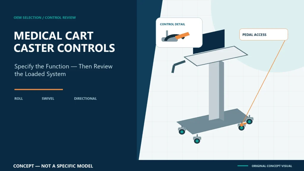
Medical equipment cart caster brakes should be specified from the complete loaded system and its workflow—not by wheel diameter or brake labels alone. Buyers should define how the cart travels, turns, parks and is released; which casters swivel; what each pedal controls; whether brakes remain accessible after accessories are installed; and how the approved three-, four- or five-caster base will be evaluated on representative floors.
CRF focuses on aluminum alloy medical equipment carts with three-, four- and five-caster bases. This guide concerns equipment-support carts, not three-wheel walkers or other patient mobility aids. It is procurement education, not medical, safety or regulatory advice. Qualified engineering, safety, user and regulatory teams must define project-specific requirements and acceptance criteria.
Why “locking caster” is not a complete specification
Supplier terminology can hide important functional differences. A wheel brake may stop wheel rotation while leaving the caster free to swivel. A total-lock mechanism generally restrains both rolling and swiveling. A directional lock restrains swivel rotation to support tracking while still permitting wheel rotation. Designs, controls and terminology vary, so the RFQ should describe required behavior and request confirmation in the drawing and component specification.
Do not assume that every caster needs the same function. The appropriate combination depends on the cart geometry, intended steering method, parking task, equipment configuration and route. Likewise, a brake count alone does not prove that a parked cart meets the finished system’s requirements.
Start with four operating states
1. Transport
Define who pushes the cart, from which handle, and over which floors, thresholds, doorways and elevators. Record the installed equipment, accessories and cable transport position. The caster arrangement should be reviewed while the cart is loaded as intended—not only as an empty frame.
2. Turning and final approach
Document tight turns, side approaches and positioning beside other equipment. Swivel freedom may help local maneuvering, while a directional function may assist tracking on a longer route. Neither is universally preferable. The complete layout, handle, base arms and user sightline determine practical behavior.
3. Parked operation
Define what “parked” must mean for the application. Does the requirement concern rolling, swiveling or both? Which external actions might be applied during use? Where will the cart stand, and is the floor level? The responsible team must establish and validate the finished-system criteria.
4. Release and departure
Brake pedals must remain visible and accessible in the approved configuration. A basket, cable loop or base-mounted component should not block operation. The release sequence should be clear, and the cart should not be moved with a brake unintentionally engaged.
Compare brake functions without making assumptions
| Function to confirm | Procurement question | Evidence to request |
|---|---|---|
| Wheel restraint | Does engagement stop wheel rotation? | Component specification and sample observation |
| Swivel restraint | Does engagement also stop caster swivel? | Drawing callout and functional review |
| Directional control | Is a caster intended to track in a selected direction? | Defined orientation and operating sequence |
| Pedal access | Can the intended user engage and release it after all accessories are fitted? | Loaded configuration review |
| Status recognition | Can users tell whether the control is engaged? | Sample inspection and user review |
| Mounting interface | Is the stem, plate or other interface controlled? | Approved interface drawing and BOM |
| Replacement | Can the exact approved caster be identified and replaced? | Part identifier and service instruction |
Commercial caster references can explain functional categories, but they do not validate a CRF cart or a finished medical system. Confirm the actual selected component and its interaction with the approved base.
Wheel count does not settle brake selection
Three-, four- and five-caster equipment-cart bases create different contact geometries and control locations. However, wheel count alone does not establish stability, braking effectiveness, maneuverability or suitability.
Review:
- equipment weight and center-of-gravity inputs from the responsible source;
- base dimensions and caster contact locations;
- caster diameter, tread, bearing, swivel and mount specifications;
- the number, position and function of brake or directional controls;
- handle position and user sightline;
- accessories, cables and components near the base;
- representative floors, transitions, routes and parking locations; and
- the finished assembly under foreseeable operating and transport configurations.
A five-caster base is not automatically more stable, easier to steer or better braked than a three- or four-caster base. The complete configuration requires its own review and verification.
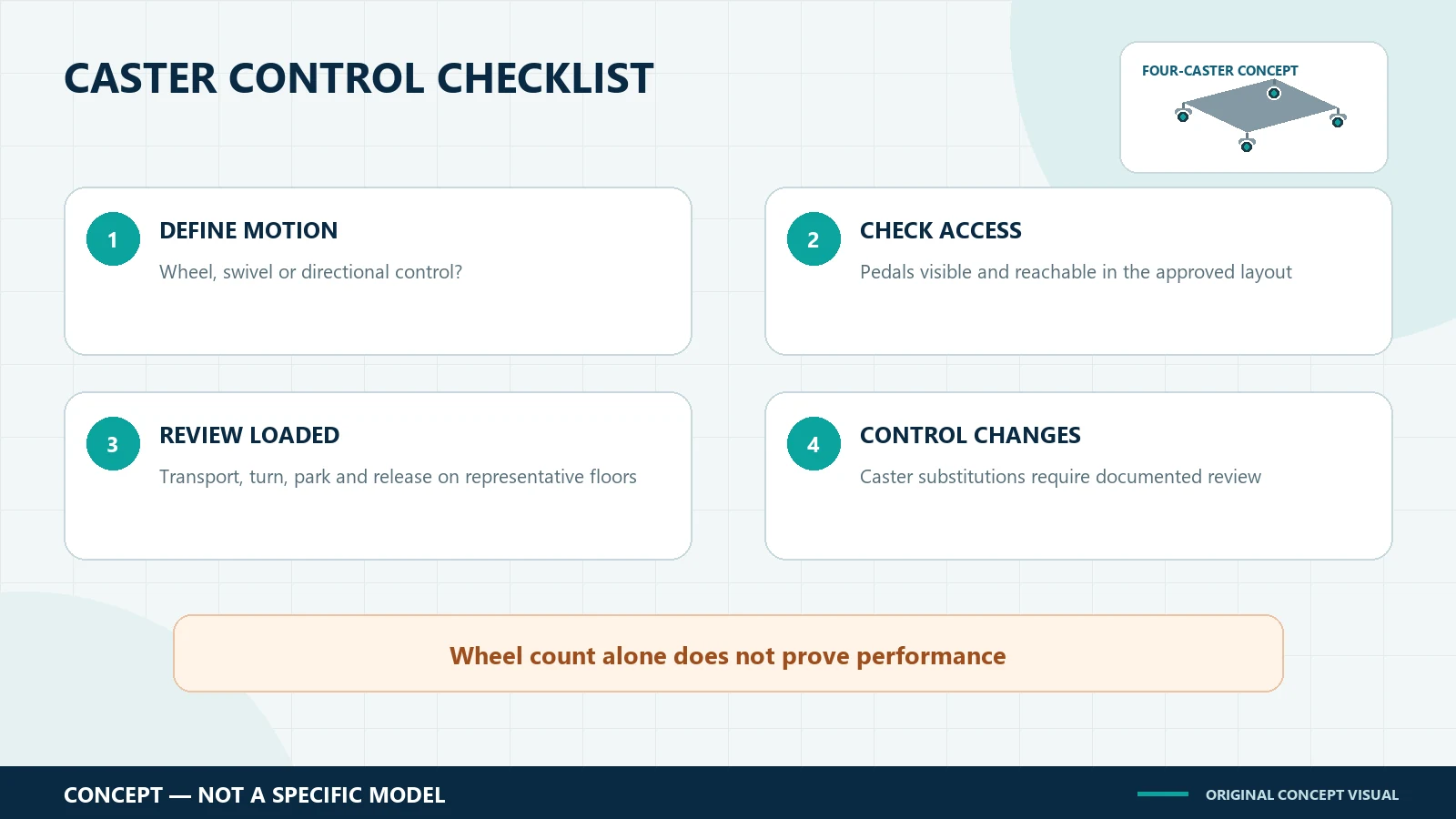
Build a caster-control specification
Define behavior before selecting a part
Write requirements as observable functions: which wheel or swivel motion is restrained, how the user engages the control, and in which cart state it is used. Avoid relying on terms such as “medical-grade,” “silent” or “heavy-duty” without supporting criteria.
Freeze interfaces in controlled documents
Record the caster supplier reference or approved equivalent process, mount interface, fasteners, orientation, control position and relevant drawing revision. A visually similar replacement can differ in offset, swivel behavior, tread, mounting geometry or pedal clearance.
Evaluate the representative loaded configuration
Use the intended device, bracket, trays, accessories and cable route, or a qualified representative configuration approved by the project team. Review starting, steering, turning, stopping, parking and release on representative surfaces. Record observations and unresolved issues.
Control changes
Reassess relevant criteria if caster model, wheel material, offset, mount, base geometry, equipment position, accessory layout or brake function changes. Treat caster substitution as a controlled engineering decision rather than an informal purchasing swap.
OEM RFQ checklist
Send the cart manufacturer:
- equipment and accessory drawings;
- equipment mass and center-of-gravity inputs;
- preferred three-, four- or five-caster concept, if already selected;
- transport, turning, parking and operating scenarios;
- floor types, thresholds and route constraints;
- required wheel, swivel or directional restraint behavior;
- pedal-access and status-recognition expectations;
- cleaning and service-access requirements;
- sample evaluation conditions and acceptance ownership; and
- documentation, replacement-part and change-control requirements.
Ask the supplier to list assumptions and open inputs. The final quotation and drawing should identify the actual configuration rather than imply universal compatibility.
CRF references for project discussion
The CRF 4-Wheel Universal Ultrasound/ECG Medical Cart is a four-wheel equipment-support reference. The CRF Five-Wheel Medical Monitor Cart is a separate five-wheel reference. These listings do not prove compatibility, brake performance, stability or availability for another project.
Browse the current CRF medical cart collection to identify a discussion starting point, then confirm the device, base, caster controls and acceptance scope against project documents.
Limits of this guide
This article supplies no load rating, slope, stopping distance, force limit, universal brake count, alloy grade, test result, certification, price, stock or delivery date. It does not claim that any brake category is universally safest. Finished-system obligations depend on intended use, configuration and destination market.
FAQ
What is the difference between a wheel brake and a total-lock caster?
A wheel brake restrains wheel rotation; a total-lock design generally restrains both wheel rotation and caster swivel. Terminology and mechanisms vary, so confirm the selected component’s documented function.
Should every caster on a medical equipment cart have a brake?
There is no universal answer in this guide. The project team should define required behavior from the base geometry, loaded configuration, workflow and parking conditions, then verify the selected arrangement.
Does a directional lock park the cart?
A directional lock is typically intended to restrain swivel orientation while permitting rolling. Do not treat it as a parking brake unless the selected component documentation and project validation establish otherwise.
Is a five-caster cart better braked than a four-caster cart?
Not automatically. Brake function, caster positions, base geometry, load distribution, controls and test conditions all matter. Evaluate the actual loaded assembly.
Discuss your caster-control requirements with CRF
Explore CRF’s aluminum medical equipment carts and send an RFQ through the contact page or relevant product page, or email sales@szcrftech.com. Include the equipment drawing, loaded configuration, route, parking task, preferred base concept and required caster-control behavior. Ask CRF to identify open inputs and propose a drawing and sample-review scope.